Micromirror system with electrothermal actuator mechanism

a micromirror and actuator technology, applied in the field of digital micromirror technology, can solve the problems of dmd image quality affecting, image degradation, size and cost of dmds, etc., and achieve the effect of effective orienting the micromirror, less expensive, and better contrast and image quality

Active Publication Date: 2007-10-25
TEXAS INSTR INC
View PDF0 Cites 6 Cited by
  • Summary
  • Abstract
  • Description
  • Claims
  • Application Information

AI Technical Summary

Benefits of technology

[0012] The presence of the bimetallic actuators allows stiction forces to be overcome mechanically, as the bimetallic arms basically pry the micromirror away from the electrode stop upon heating. This allows the electrodes to effectively orient the micromirror (by controlling which way the micromirror tilts about the hinge) using much lower voltages (since the electrostatic force applied by the electrodes does not have to be strong enough to overcome stiction, but merely to move the micromirror once it is in a neutral position). Using lower voltages allows for miniaturization of DMD devices, since the transistors sending power to each electrode can be smaller. Such lower voltage requirements also allow DMDs to be built less expensively, since smaller, less expensive transistors can handle the lower voltages. The disclosed embodiments also carry the potential for better contrast and image quality, since the lower voltage requirement and the constant voltage applied to the micromirrors allows for a smaller gap between the micromirrors without the concern that micromirrors will be attracted to each other. In addition, the disclosed embodiments enable a faster pixel, by overcoming stiction to allow the micromirrors to switch more quickly between bistable positions. Again, this speed advantage may improve image reproduction quality.

Problems solved by technology

Nevertheless, DMD image quality has historically been impacted by stiction, which is a tendency for each micromirror element to stick when in contact with the electrode contact surface (against which the electrostatic force holds the micromirror in either the open or closed position).
This stiction is associated with Van der Waal's forces, surface contamination, and surface friction, and can cause a delay in the movement of the micromirrors, resulting in possible image degradation.
But the use of high-voltage pulses to overcome stiction acts as a limiting factor concerning the size and expense of DMDs, since the transistors operating the electrodes must be capable of handling the high voltage needed to overcome stiction.
Likewise, the use of high voltages requires a sufficient gap between each of the micromirrors in order to prevent micromirrors with different voltages from being mutually attracted, and this gap requirement acts as a limitation on the contrast available for the DMD.
So, problems associated with the present high-voltage pulse technique for overcoming stiction have led to investigations into alternative techniques for addressing stiction problems.

Method used


Image

  • Micromirror system with electrothermal actuator mechanism
  • Micromirror system with electrothermal actuator mechanism
  • Micromirror system with electrothermal actuator mechanism

Examples


Embodiment Construction

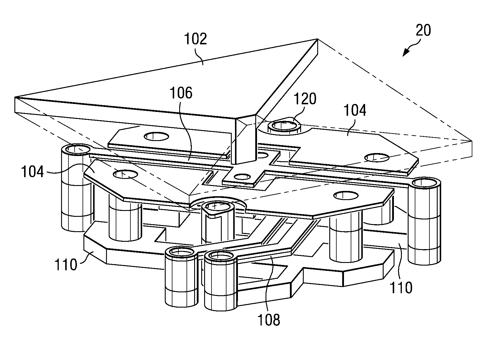
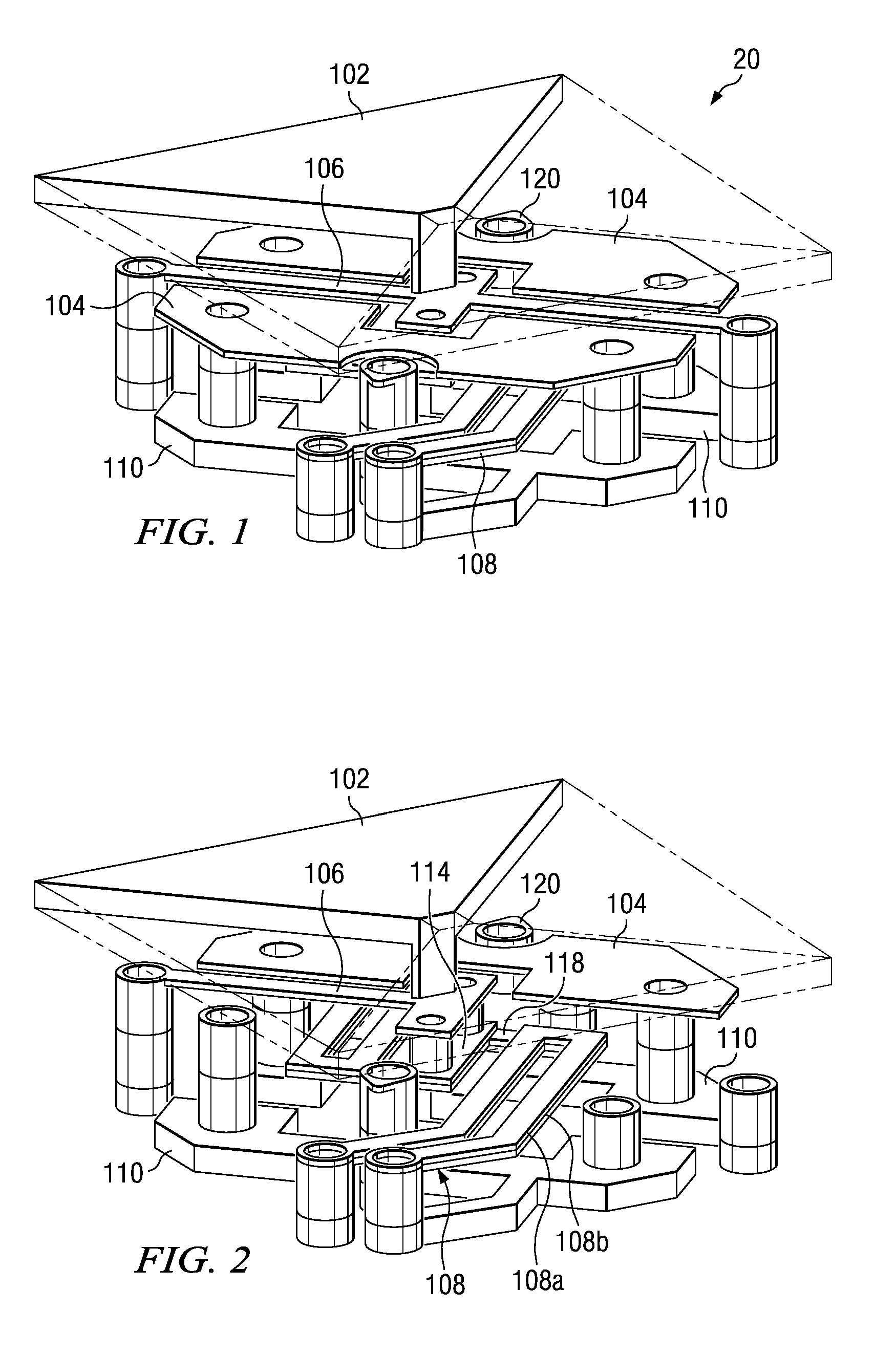
[0022] As shown in FIG. 1, one embodiment of DMD pixel device 20 couples electrothermal actuator elements with electrostatic actuator elements, in order to jointly orient a bistable micromirror 102 (which is shown with a cutaway of ¾ of the micromirror 102 with the remainder of the micromirror 102 illustrated by ghosted line features). The disclosed electrostatic actuator uses electrodes on either side of the micromirror pivot to attract the micromirror 102, pulling it downward into contact with a stop rest 120. This electrostatic orientation of the micromirror 102 is accomplished by applying a constant voltage to the micromirror 102, and selectively applying a voltage to the electrodes. The voltage difference results in electrostatic attraction, orienting the micromirror 102 into either an open or closed position.

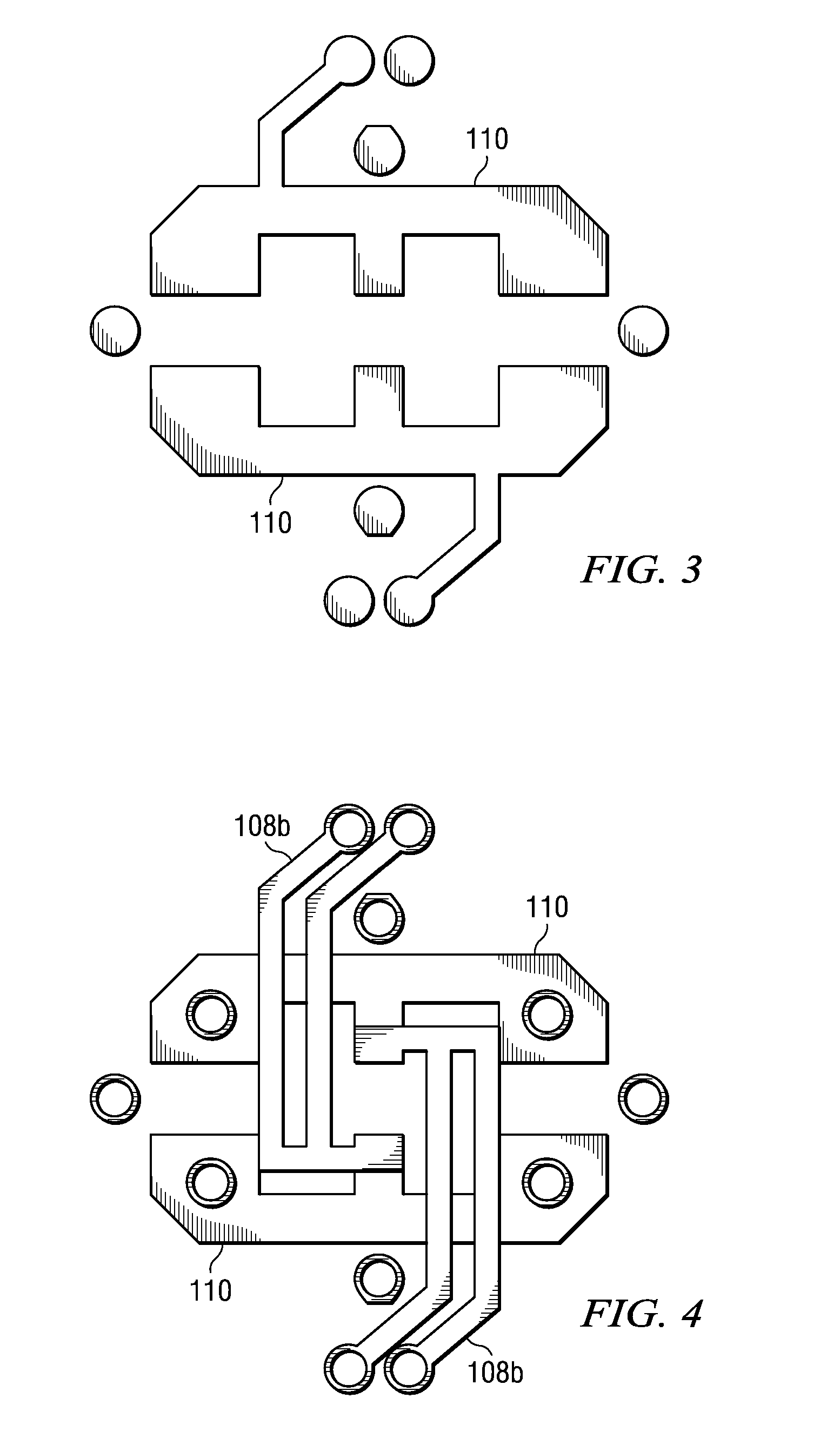
[0023] While this electrostatic attraction is one element of the described device 20, electrothermal actuators are further provided to assist in orienting the micromirror...


PUM


Abstract

The disclosed embodiments combine an electrothermal actuator system with an electrostatic attraction system, in order to orient bistable micromirrors in digital micromirror devices (DMDs). The micromirror, pivotally supported, can switch between two orientations. While typical DMD systems use electrostatic electrodes to orient the micromirror, stiction forces can restrict micromirror motion, affecting optical performance. The disclosed embodiments use an electrothermal actuation system to mechanically assist the electrodes, overcoming stiction without the need for a high-voltage reset pulse.

Description

FIELD OF THE INVENTION [0001] The disclosed embodiments herein relate generally to the use of digital micromirror technology to provide image display capability as part of a digital light projection system, and more particularly to an electrothermal actuator mechanism to improve the control characteristics of micromirror orientation. BACKGROUND OF THE INVENTION [0002] Digital light projection (DLP) technology has been increasingly used for optical display systems, such as those found in upscale home theater systems. This technology has begun replacing traditional cathode ray tube technology, since it can provide high image quality, without the bulk and power requirements associated with the older technology. [0003] In essence, a DLP system is comprised of a digital micromirror device (DMD), made up of an array of thousands or even millions of bistable mirror elements, interacting with a light source and a projection surface. Each of the mirror elements of the DMD may switch between ...

Claims


Application Information

Patent Timeline
Patent Type & Authority Applications(United States)
IPC IPC(8): G02B21/06
CPCG02B26/0866
Inventor KMECKO, IVAN
Owner TEXAS INSTR INC
Why Eureka
Try Eureka