Hybrid display device

a display device and hybrid technology, applied in the direction of optical system scanning details, organic semiconductor devices, discharge tubes/lamp details, etc., can solve problems such as difficulty in properly aligning substrates

Inactive Publication Date: 2005-02-15
BUFFALO PATENTS LLC
View PDF60 Cites 58 Cited by
  • Summary
  • Abstract
  • Description
  • Claims
  • Application Information

AI Technical Summary

Benefits of technology

[0014]According to still another aspect of the invention, a display device includes a front panel and a back panel with a light co

Problems solved by technology

However, one problem with polymeric substrate displays is the difficulty of properly aligning

Method used


Image

  • Hybrid display device
  • Hybrid display device
  • Hybrid display device

Examples


Embodiment Construction

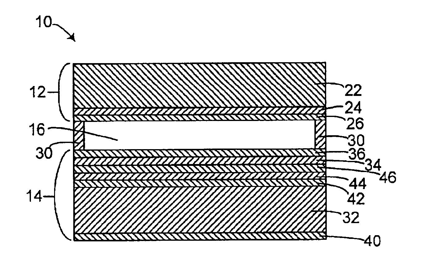
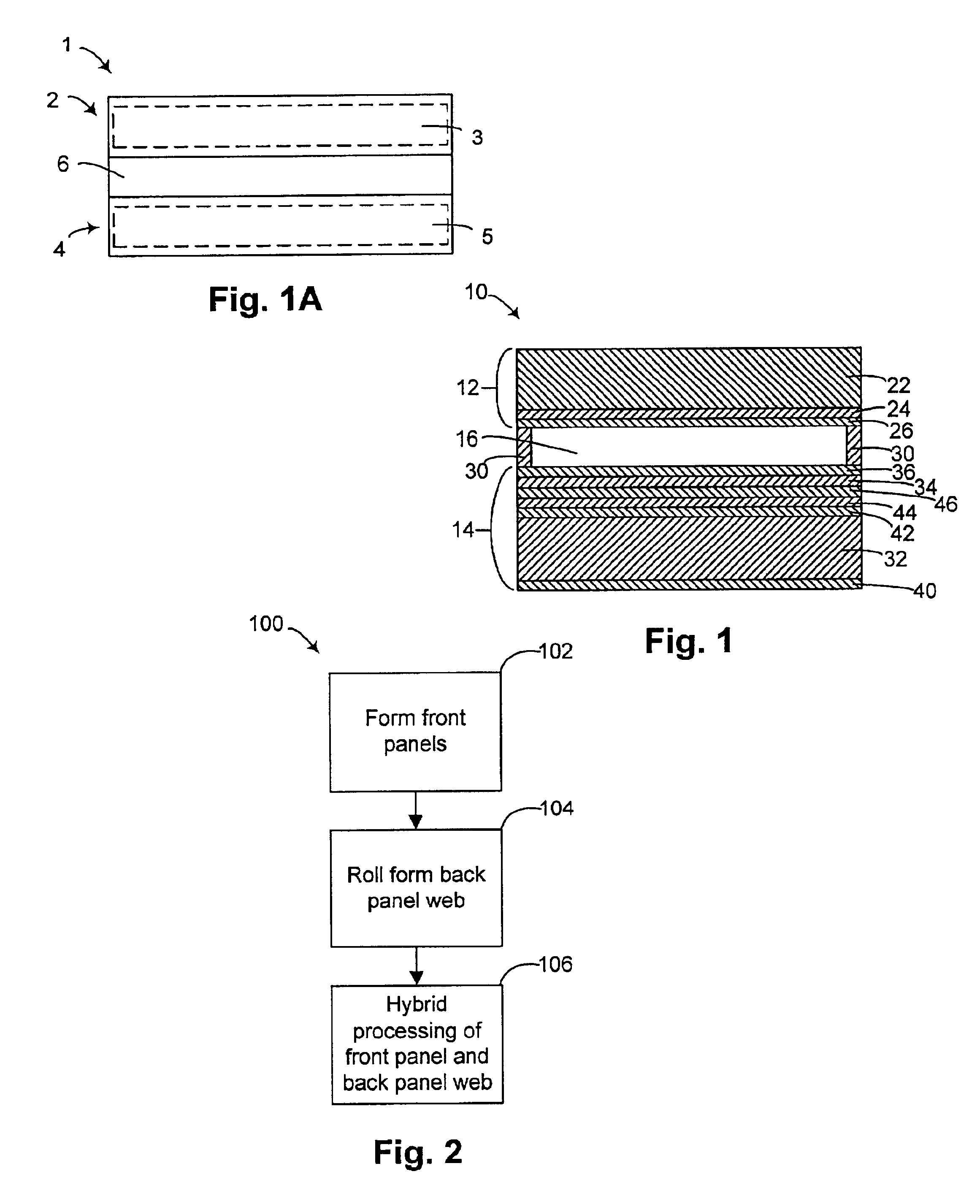
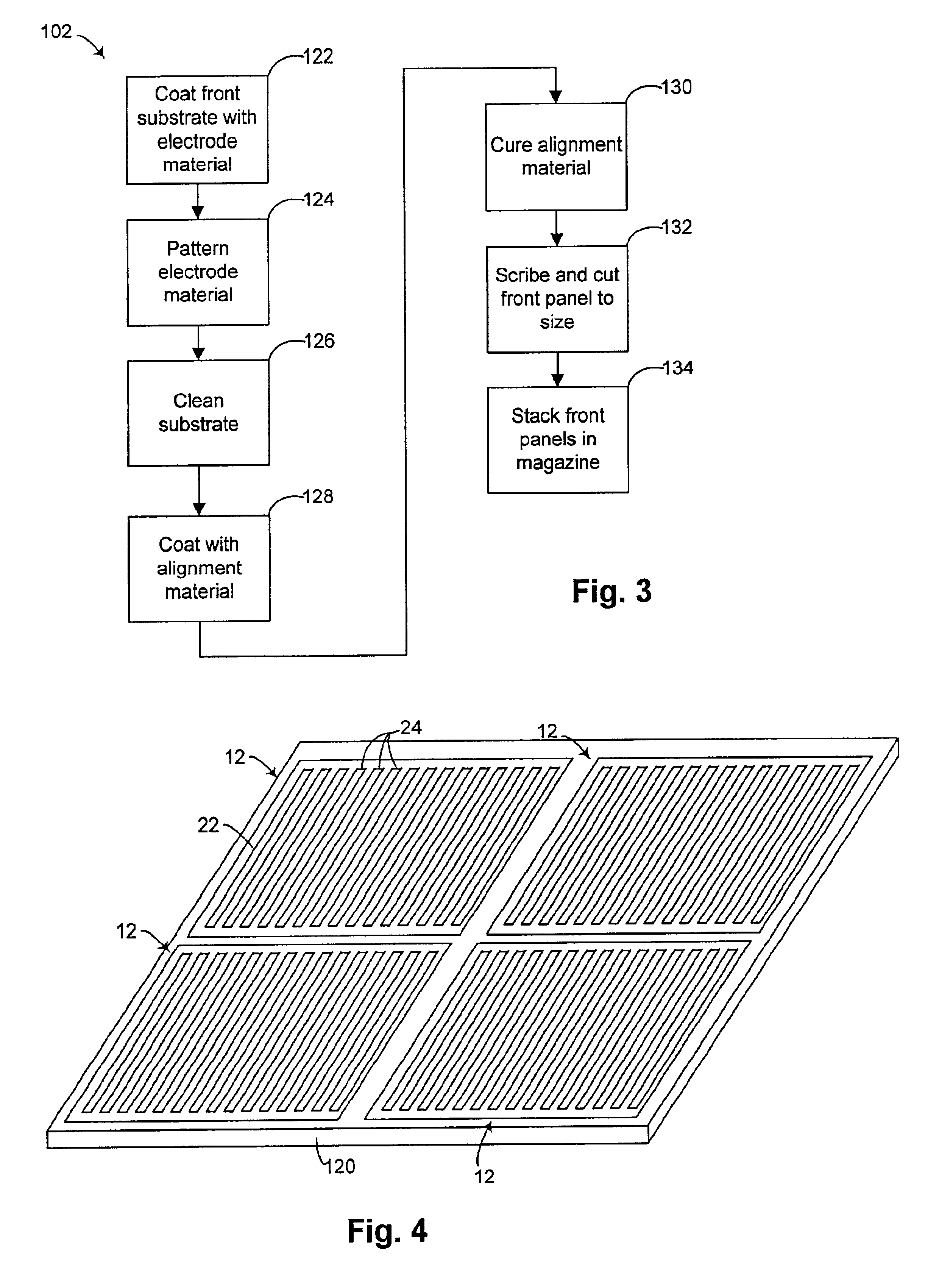
[0042]Referring to FIG. 1A, a display device 1 includes a front panel 2 having a rigid front substrate 3, and a back panel 4 having a flexible back substrate 5. A light control material 6 is between the front panel 2 and the back panel 4. As used in this patent application, a “light control” material can perform one or more of the following functions: emission of light, and regulation of light from another source by transmission, reflection, and / or refraction. Exemplary types of display devices include LCD devices, for which the light control material is a liquid crystal material, and polymer light emitting devices (PLEDs) and organic light emitting devices (OLEDs), for which the light control material is a light emitting material. An exemplary material for the front substrate is glass, and an exemplary material for the back substrate is a polymer film. The device may be formed by forming the back panels in a series of roll-to-roll operations, and then placing discrete front panels ...


PUM


Abstract

A display includes a front panel and a back panel with a light control material in between. One of the panels includes a rigid substrate, for example made of glass or rigid plastic. The other of the panels includes a flexible substrate, for example made of a flexible plastic film. The panel with the flexible substrate may be made by a roll-to-roll process, with various fabrication operations formed while the flexible substrate is still part of a web of material. The panel with the rigid substrate may be separately fabricated, then combined with the other panel on the web through a pick and place operation that accurately locates the front panel relative to the back panel. The display may be any of a variety of displays, such as liquid crystal displays (LCDs), and electroluminescent displays, such as polymer light emitting devices (PLEDs) and organic light emitting devices (OLEDs).

Description

[0002]This application claims the benefit of U.S. Provisional Application No. 60 / 300,682, filed Jun. 25, 2001, which is incorporated by reference in its entirety.BACKGROUND OF THE INVENTION[0003]1. Technical Field of the Invention[0004]The invention relates to optical display devices, and to methods for making the same.[0005]2. Background of the Related Art[0006]Liquid crystal display (LCD) devices are one example of well-known display devices that are useful in a number of applications where light weight, low power and a flat panel display are desired. Typically, these devices comprise a pair of sheet-like, glass substrate elements or “half-cells” overlying one another with liquid crystal material confined between the glass substrates. The substrates are sealed at their periphery with a sealant to form the cell or device. Transparent electrodes are generally applied to the interior surface of the substrates to allow the application of an electric field at various points on the subs...

Claims


Application Information

Patent Timeline
IPC IPC(8): G02F1/13G02F1/1341H01L27/32H01L27/28G02F1/1333H01L51/52H01L51/56H01L51/50
CPCG02F1/1341H01L27/3244H01L51/52H01L51/56H01L27/3281G02F1/133305G02F2001/133354G02F2001/133368Y10S428/917H01L51/525H01L2251/5338H01L2251/566G02F1/133354G02F1/133368H10K59/129H10K59/12H10K59/17H10K50/80H10K50/8428H10K71/851H10K2102/311H10K71/00
Inventor GRACE, ANTHONY J.DRAIN, KIERAN F.SASAKI, YUKIHIKO
Owner BUFFALO PATENTS LLC
Why Eureka
Try Eureka