Integrated transformer

a transformer and integrated technology, applied in the direction of transformer/inductance coil/winding/connection, transformer/inductance/transformer, continuous variable inductance/transformer, etc., can solve the problem of relatively high cost of discrete transformer

Inactive Publication Date: 2005-02-15
INTEL CORP
View PDF52 Cites 69 Cited by
  • Summary
  • Abstract
  • Description
  • Claims
  • Application Information

AI Technical Summary

Problems solved by technology

Because discrete transformers result in losses, for example, due to parasitic capacitance and resistance in connecting them to an integrated circuit and because discrete transformers incur a relatively high cost for assembly, transformers are preferably fabricated on-chip, that is integrated on an integrated circuit, and / or in a package housing an integrated circuit.

Method used


Image

  • Integrated transformer
  • Integrated transformer
  • Integrated transformer

Examples


Embodiment Construction

The following detailed description sets forth an embodiment or embodiments in accordance with the present invention for an integrated transformer. In the following description, details are set forth such as specific materials, parameters, etc. in order to provide a thorough understanding of the present invention. It will be evident, however, that the present invention may be practiced without these details. In other instances, well-known process steps, equipment, etc. have not been described in particular detail so as not to obscure the present invention.

Spiral Inductor Structure

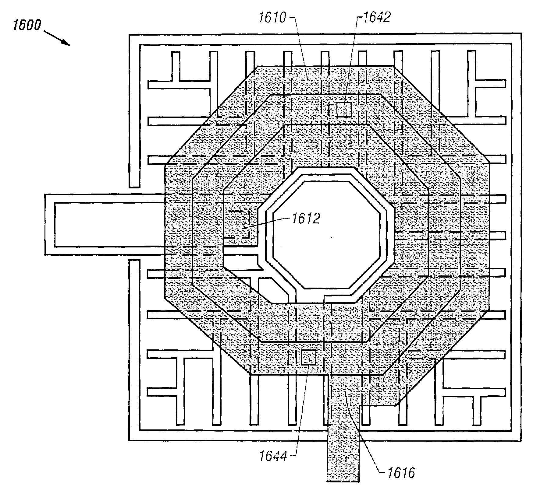
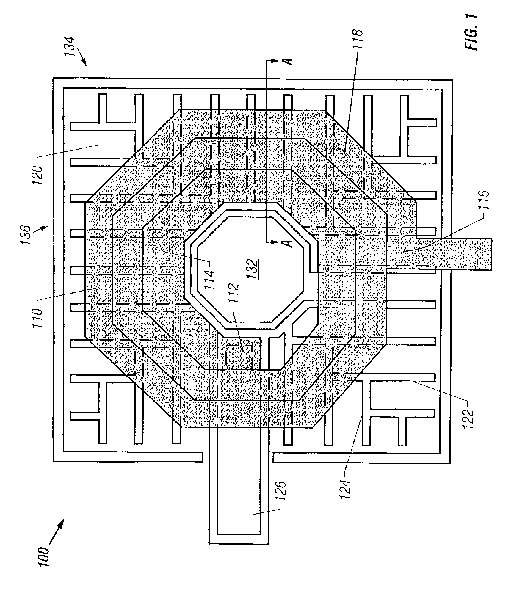
FIG. 1 illustrates, for one embodiment, an integrated inductor 100. Integrated inductor 100 comprises a generally spiral-shaped conductor 110 defining a signal path along which current may flow to generate an electromagnetic field around conductor 110. Current may flow through conductor 110 by applying a voltage potential across an innermost node 112 near the beginning of an innermost turn 114 of conductor 1...


PUM

PropertyMeasurementUnit
thicknessaaaaaaaaaa
thicknessaaaaaaaaaa
thicknessaaaaaaaaaa

Abstract

A transformer comprises a substrate comprising a semiconductor material, a first conductor over the substrate, a second conductor over the substrate, and a magnetic layer over the substrate. The first conductor defines a generally spiral-shaped signal path having at least one turn. The second conductor defines a generally spiral-shaped signal path having at least one turn.

Description

BACKGROUND OF THE INVENTIONField of the InventionThe present invention relates generally to the field of electrical transformers. More particularly, the present invention relates to the field of electrical transformers for integrated circuits (ICs) and IC packages.DESCRIPTION OF RELATED ARTElectrical transformers are typically used in a variety of microelectronic circuit applications such as, for example, power converters, power delivery devices, power isolation devices, and radio frequency (RF) and microwave circuitry including matching networks, oscillators, amplifiers, and filters. Because discrete transformers result in losses, for example, due to parasitic capacitance and resistance in connecting them to an integrated circuit and because discrete transformers incur a relatively high cost for assembly, transformers are preferably fabricated on-chip, that is integrated on an integrated circuit, and / or in a package housing an integrated circuit.BRIEF DESCRIPTION OF THE DRAWINGSThe...

Claims


Application Information

Patent Timeline
Patent Type & Authority Patents(United States)
IPC IPC(8): H01F17/00H01F41/04H01L21/02H01L23/522H01L23/58H01L23/64H01L23/552H01L23/52H01L27/08
CPCH01F17/0006H01F41/042H01F41/046H01L23/522H01L23/5227H01L23/552H01L23/645H01L27/08H01L28/10H01F2017/0046H01F2017/008H01L2924/0002H01L2924/00
Inventor GARDNER, DONALD S.
Owner INTEL CORP
Why Eureka
Try Eureka