Systems and processes for decoding chain reaction codes through inactivation

a chain reaction and chain reaction technology, applied in the field of systems and methods for decoding information additive codes and multi-stage information additive codes, can solve the problems of gaussian elimination running time prohibitively large, decoding process may stop prematurely, and decoder may flag an error

Inactive Publication Date: 2005-02-15
QUALCOMM INC
View PDF5 Cites 112 Cited by
  • Summary
  • Abstract
  • Description
  • Claims
  • Application Information

AI Technical Summary

Benefits of technology

FIG. 5 illustrates a first embodiment of the source symbol selection and deactivation process 320 illustrated in FIG. 3. Initially at 321, an active source symbol is selected which is associated with an output symbol of degree two or higher (i.e., an output symbols associated with two or more source symbols). The manner by which a particular source symbol is selected from among a number of similar source symbols is described in greater detail below. Next at 322, the particular source symbol selected is deactivated. Subsequently at 323, determination is made as to whether any output symbols of degree one exist for decoding. In some embodiments, the preceding deactivation will produce one or more output symbols of degree one. In other embodiments, the preceding deactivation will not result in an output symbol of degree one. In the later case, the process repeats the process of 321-323 as described below.

Problems solved by technology

In some instances, the decoding process may stop prematurely and the decoder may flag an error.
However, the running time of Gaussian elimination may be prohibitively large for applications where fast decoding is desired, especially when the number of unrecovered input symbols at the time when no more output symbols of degree one are found is large.
This would lead to a decoding algorithm whose computational overhead is substantially larger than a chain reaction decoder, and may therefore be undesirable in certain applications.
For example, it may enforce the average degree of an output symbol to be higher than otherwise, and thus may lead to a decrease in the performance of the encoder and of the decoder.
More generally, this decoding procedure forces the design of the weight table to be in such a way as to guarantee the success of the abovementioned decoding algorithm with high probability, and hence may put restrictions on the set of possible weight tables.

Method used


Image

  • Systems and processes for decoding chain reaction codes through inactivation
  • Systems and processes for decoding chain reaction codes through inactivation
  • Systems and processes for decoding chain reaction codes through inactivation

Examples


first embodiment

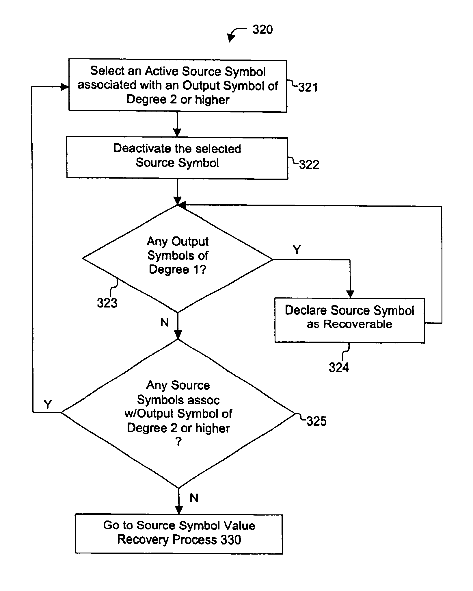
FIG. 4A illustrates the start-up process 310 illustrated in FIG. 3. Initially at 311, a determination is made as to whether any output symbols of degree one are present. If so, the source symbol associated with that output symbol is recovered at 312. The process then returns to 311, where a subsequent determination is made as to whether any other output symbols of degree one remain in the code. If at 311 no output symbols of degree one remain, the process proceeds to the source symbol selection and deactivation process 320, further described below.

second embodiment

FIG. 4B illustrates the start-up process 310 illustrated in FIG. 3. In this embodiment, an output symbol of degree one is identified at 315. Subsequently at 316, the source symbol associated with the identified output symbol is recovered. Next at 317, a determination is made as to whether any other output symbol of degree one remains. If so, the process returns to 316 where the associated source symbol is recovered. If not, the process proceeds to the source symbol selection and deactivation processes described below.

In one embodiment of the invention, recovery of source symbols described in 310 occur temporally before the recovery of deactivated and recoverable source symbols referred to in 320. However, the invention is not limited thereto, and recovery of the source symbols identified in 310 may occur substantially concurrently with the recovery of the deactivated and recoverable source symbols in process 330 in alternative embodiments of the present invention.

FIG. 5 illustrates ...


PUM


Abstract

A method for processing a chain reaction codes includes first selecting a source symbol which is associated an output symbol of degree two or higher (i.e., an output symbol which is itself associated with two or more input symbols), and subsequently deactivating the selected source symbol in an attempt to produce an output symbol of degree one. The inactivation process can be repeated either successively until an output symbol of degree one is identified, and / or whenever the decoding process is unable to locate an output symbol of degree one.

Description

BACKGROUND OF THE INVENTIONThe present invention relates to systems and methods for decoding data, and more particularly, to systems and methods for decoding information additive codes and multi-stage information additive codes, herein referred to collectively as “chain reaction codes.”Chain reaction codes have been described previously in the assignee's patents, such as U.S. Pat. No. 6,307,487 entitled “Information Additive Code Generator and Decoder for Communication Systems” (hereinafter “Luby I”), and U.S. patent application Ser. No. 10 / 032,156, entitled “Multi-Stage Code Generator and Decoder for Communication Systems” (hereinafter “Raptor”). As described therein, chain reaction decoding is a unique form of forward error-correction that enables data reconstruction from a received data set of a given size, without regard to the particular data packets received. Communication systems employing chain reaction codes are able to communicate information much more efficiently compared...

Claims


Application Information

Patent Timeline
Patent Type & Authority Patents(United States)
IPC IPC(8): H03M13/00H03M13/47H03M13/11H03M13/19H03M13/37
CPCH03M13/1191H03M13/47H03M13/3761H03M13/1102H03M13/19
Inventor SHOKROLLAHI, M. AMINLASSEN, SORENKARP, RICHARD
Owner QUALCOMM INC
Why Eureka
Try Eureka