Image forming apparatus

Active Publication Date: 2005-02-15
CANON KK
View PDF13 Cites 34 Cited by
  • Summary
  • Abstract
  • Description
  • Claims
  • Application Information

AI Technical Summary

Benefits of technology

The present invention has been made in order to solve the above-noted problem peculiar to the prior art, and an object thereof is to provide an image forming apparatus in

Problems solved by technology

In the above-described image forming apparatus, the storing portion s

Method used


Image

  • Image forming apparatus
  • Image forming apparatus
  • Image forming apparatus

Examples


first embodiment

A first embodiment of the present invention will hereinafter be described with reference to the drawings.

FIG. 3 is a cross-sectional view showing the construction of a color laser printer (hereinafter referred to as the laser printer) which is an image forming apparatus according to the present embodiment. The reference numeral 201 designates the laser printer, and the reference numeral 202 denotes a host computer. The present embodiment is an example of a four-drum type color laser printer. This color laser printer is provided with image forming portions for four colors to form a color image comprising images of four colors (yellow: Y, magenta: M, cyan: C, and black:BK) superimposed one upon another.

The image forming portions comprise toner cartridges 207 to 210 having photosensitive drums 301-304 as image bearing members, and scanner units 205 and 206 having laser diodes (corresponding to laser beam generating elements in the appended claims) for generating laser beams as image ex...

second embodiment

A “pseudo / BD producting method” which is a second embodiment will hereinafter be described.

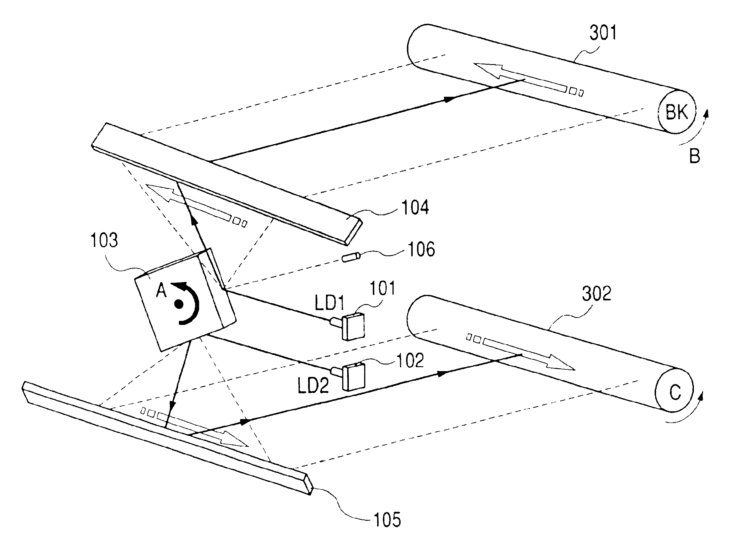
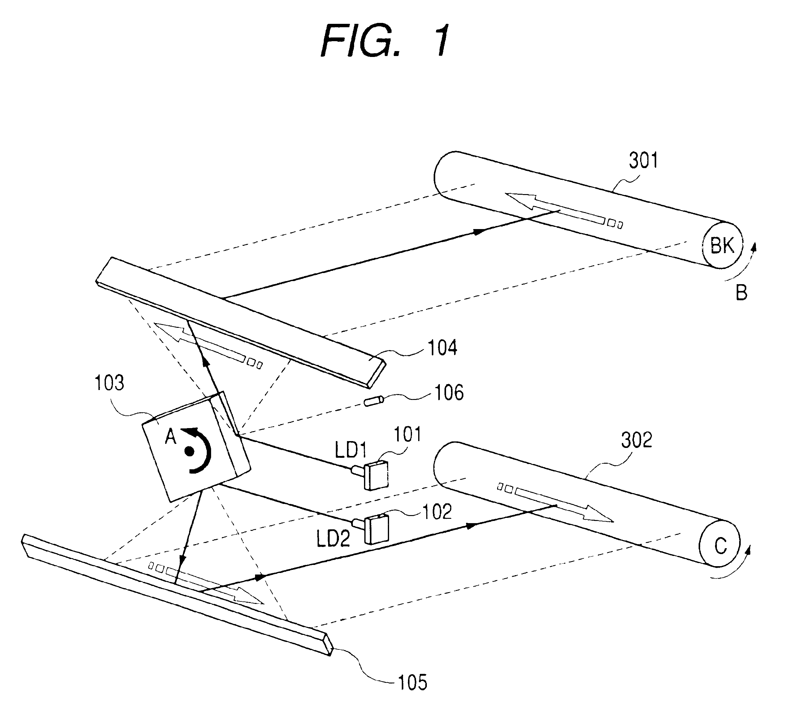
FIG. 8 shows a scanner unit in the second embodiment. The difference of the second embodiment from the first embodiment is that LD2 (702) is on the side opposite to LD1 (101) with respect to the polygon 103. A laser beam from the laser diode LD1 and a lasa beam from the laser diode LD2 are applied to the polygon mirror 103 at a time from the right side and from the left side in FIG. 8, respectively. In the other points, the construction of the second embodiment is similar to the construction of the first embodiment. In this construction, a method of calculating correction values of each four sides and a pseudo BD producing method will be described with reference to the timing chart of FIG. 9 and FIG. 11 showing the relation among the polygon mirror, the laser and the BD sensor. Here again is shown an embodiment of the four-side polygon. The number of the sides of the polygon is unnecessary.

Th...

third embodiment

Description will now be made of a “pseudo BD producing method” which is a third embodiment of the present invention.

FIG. 18 is a cross-sectional view showing the construction of a color laser printer (hereinafter referred to as the laser printer) which is an image forming apparatus according to the present embodiment. FIG. 17 shows the details of a scanner unit 905 in FIG. 18. The difference of the present embodiment from the first embodiment is that the number of scanner units is one and a polygon 809 is used to effect the formation of an image of four colors.

An image forming portion comprises toner cartridges 207 to 210 having photosensitive drums 301-304 as image bearing members, and a scanner unit 905 having laser diodes (corresponding to laser beam generating elements in the appended claims) generating laser beams as light sources for image exposure. A toner cartridge is provided for each of the four colors.

Also, as regards the scanner unit 905, it is a feature of the present e...


PUM


Abstract

This invention has as its object to provide an image forming apparatus in which the number of beam detectors is decreased and which is low in cost and high in the accuracy of the registration position of an image of each color as well as high in quality. To this end, The image forming apparatus is provided with a plurality of image bearing members, an optical system having a plurality of light emitting elements suitable for generating light beams for scanning the image bearing members, a single polygon mirror suitable for deflecting the light beams generated from the plurality of light emitting elements onto the image bearing members, and a beam detector corresponding to at least one of the plurality of image bearing members, and for receiving the light beams scanned by the polygon mirror and producing a first synchronizing signal for recording an image on the relevant image bearing member, a storing portion suitable for storing therein information regarding the error of each side of the polygon mirror, and a producing unit suitable for producing a second synchronizing signal for recording an image on the image bearing member not provided with the beam detector, by delaying the first synchronizing signal outputted from the beam detector, on the basis of the value of the storing portion.

Description

BACKGROUND OF THE INVENTION1. Field of the InventionThis invention relates to an image forming apparatus using an electrophotographic process, and particularly to a color image forming apparatus for forming different color images by the use of a plurality of laser beams.2. Related Background ArtIn an image forming apparatus using an electrophotographic process, a laser beam modulated by an image signal is reflected by a scanner having a rotating polygon mirror (hereinafter sometimes abbreviated as the polygon), and scans on a photosensitive member to thereby effect image forming. As the photosensitive member, use is often made of a drum-shaped one which is called a photosensitive drum. When this process is applied to a color laser printer, a plurality of images of different colors, e.g. yellow (Y), magenta (M), cyan (C) and black (BK) are superimposed one upon another to thereby form a color image on a sheet-like medium. Constructions for achieving this superimposing technique inclu...

Claims


Application Information

Patent Timeline
IPC IPC(8): H04N1/047H04N1/053H04N1/50H04N1/113H04N1/06G03G15/00
CPCH04N1/053H04N1/506H04N1/06H04N1/1135H04N2201/0471H04N2201/04786H04N2201/04732H04N2201/04744H04N2201/04793G03G15/00
Inventor TAKAHASHI, MASAYOSHINAKAMORI, TOMOHIROTANAKA, YOSHIHIKO
Owner CANON KK
Why Eureka
Try Eureka