Strobe flash photographic illumination

a technology of flash and flash light, applied in the field of flash flash illumination of cameras, can solve the problems of inconvenient use of conventional flash illumination in many environments, document scanner occupies a significant amount of desk space, and bright flash of light from such a unit can be startling or annoying to anyone nearby,

Inactive Publication Date: 2005-02-15
HEWLETT PACKARD DEV CO LP
View PDF23 Cites 16 Cited by
  • Summary
  • Abstract
  • Description
  • Claims
  • Application Information

AI Technical Summary

Benefits of technology

Because the pulsed strobe flash appears to be a continuous light, the illumination can be much less obtrusive than a single flash synchronised with the shutter means. The illumination can be no more distracting than a person turning a light such as a desk lamp on, and then off.
The image capture means may be photographic film or at least one electronic detector array, for example a two dimensional CCD array. In most applications, it is preferred if the image capture means is a detector array, owing to the greater sensitivity at low light levels. This permits a reduction in strobe flash energy compared with that needed with many types of photographic film.
The illumination can be made less intrusive if the pulse circuitry is arranged to ramp up the perceived intensity of the steady illumination prior to the capture of the image, and / or to ramp down said intensity after capture of the image. In terms of human perception of the intrusiveness of the illumination, the ramp up in intensity gives a greater benefit than the ramp down in intensity, but most preferably the illumination is ramped both up and down in intensity.
Therefore, the camera may include an actuator to scan the field of view of the objective lens in the object plane as the control circuitry captures images of different fields of view. In this case, the strobe flash may be used to effectively freeze any relative motion between the object plane and the camera. Therefore, there is no need for the actuator to stop motion when an image is to be captured, and so the actuator may scan the field of view of the objective lens continuously, i.e. without stopping, as the control circuitry captures images of different fields of view. This simplifies the control of the actuator and allows a more rapid capture of several images one after the other.
The camera may be a hand-held camera, in which case the strobe flash will help to reduce or eliminate the effect of any camera shake.

Problems solved by technology

Although these work well and are relatively inexpensive, a document scanner occupies a significant amount of scarce desk space.
Often a person has to stand up, lean over the document, and then take the photograph, in which case, the person's body may block ambient light, thereby requiring the use of a flash even if the ambient light is bright.
Although conventional flash units are effective in dealing with these problems, a bright flash of light from such a unit can be startling or annoying to anyone nearby.
For this reason it is generally considered unacceptable to use conventional flash illumination in many environments, particularly in an office environment, where others could be disturbed by a flash.
However such cameras are still used almost exclusively for photography of people or places, and have yet to be adapted for use in office imaging applications.
One reason for this is that most electronic cameras, which normally employ two dimensional CCD arrays, have insufficient resolution to image a complete A4 size page at 300 dots per inch, the minimum that is conventionally believed necessary for reasonably high quality reproduction.
Whilst higher resolution CCDs are available in electronic cameras, they are much too expensive for a mass-market office imaging product.
As a result cameras with flash attachments and electronic cameras are not widely used in place of document scanners in an office environment.

Method used


Image

  • Strobe flash photographic illumination
  • Strobe flash photographic illumination
  • Strobe flash photographic illumination

Examples


first embodiment

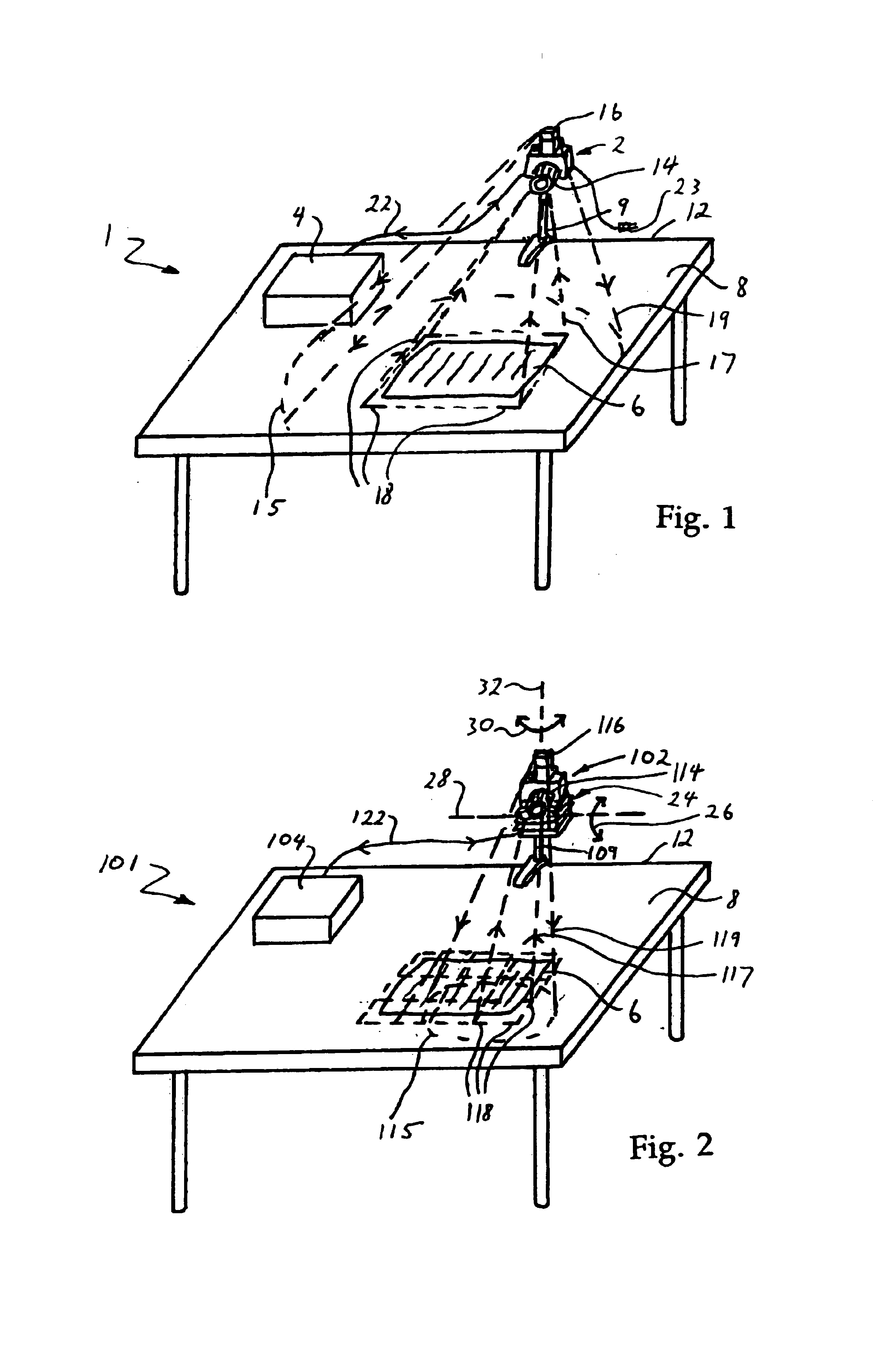
FIG. 1 shows a document imaging system 1 according to the invention, comprising a camera 2 and a camera controller unit 4 that are arranged to image a document 6 lying on a work surface 8. The camera may be hand-held, but for convenience is mounted atop a post 9 affixed to an edge 12 of the work surface 8. The document will typically be an A5, A4 or A3 size document, for example a sheet of printed paper, an open book, or a photograph.

The camera comprises an objective lens 14 and a strobe flash unit 16, both of which are directed at the document 6. The lens 14 has a field of view 18 sufficiently wide so that the lens can receive optical radiation 17 to image the entire document 6 all at once. The strobe flash unit projects visible light 19 over an area 15 sufficiently wide that the document is uniformly illuminated. As will be explained in more detail below, the camera includes an image capture means, preferably an electronic detector (see FIG. 3 reference numeral 52) and the strobe ...

second embodiment

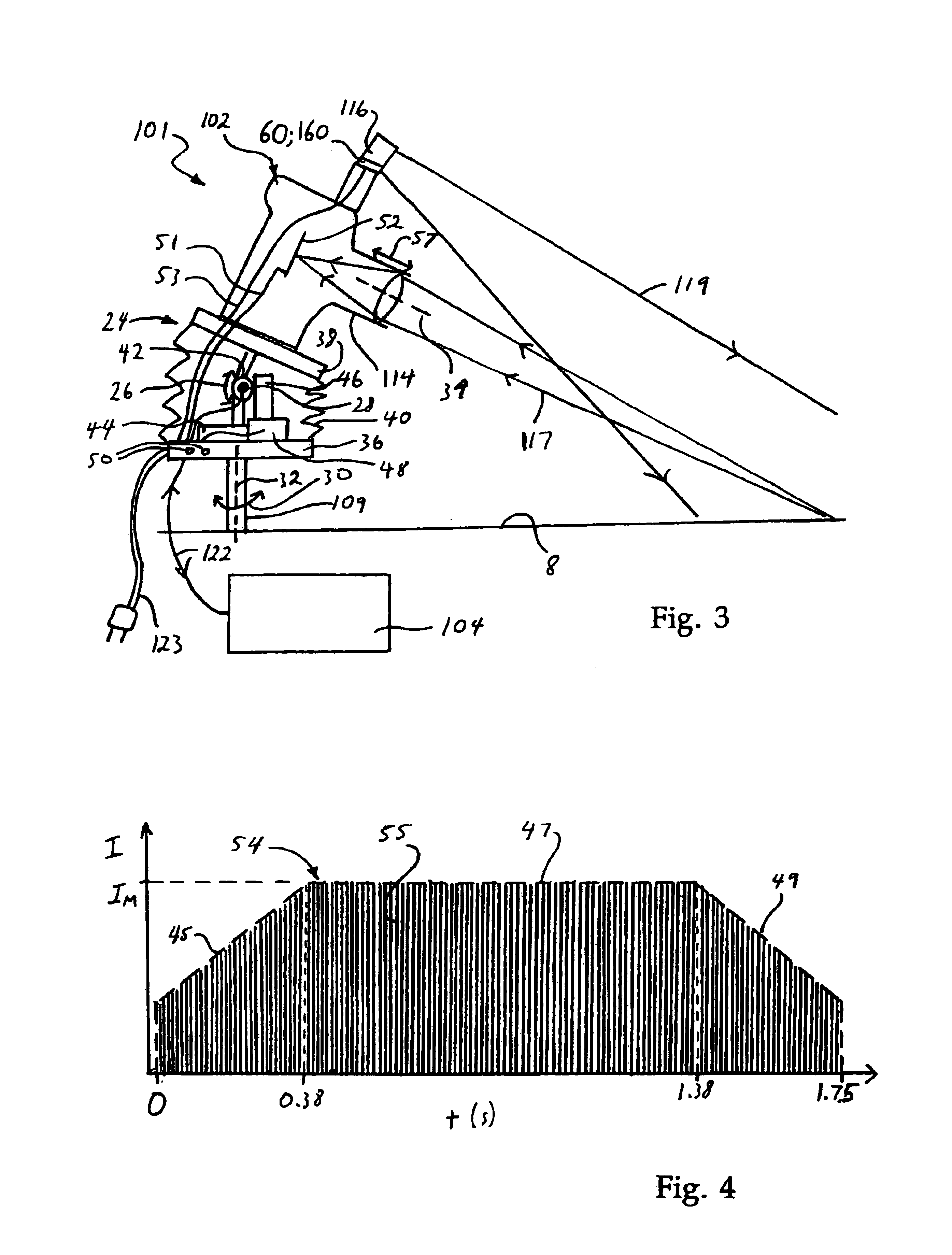
FIGS. 2 and 4 show the invention 101, in which identical features are labelled as in FIG. 1, and similar features are labelled with reference numerals incremented by 100.

The camera 102 differs from the first embodiment in that the lens field of view 118 and illuminated area 115 are narrower, and able to image only about one-twelfth of the document 6. An actuator 24 is therefore provided between the camera 102 and the post 110.

The actuator 24 has two degrees of freedom of motion 26, 30, one of which 26 is about a horizontal axis 28, and the other of which 30 is about a vertical axis 32. The horizontal axis is roughly transverse to an optical axis 34 of the lens 114. The degrees of freedom of motion 26, 30 permit the camera 102 to be moved so that the strobe flash unit 116 and lens 114 can respectively illuminate and image successively the all areas of the document 6. The degrees of freedom of motion 26, 30 need not be orthogonal, but in general it will be convenient if this is so.
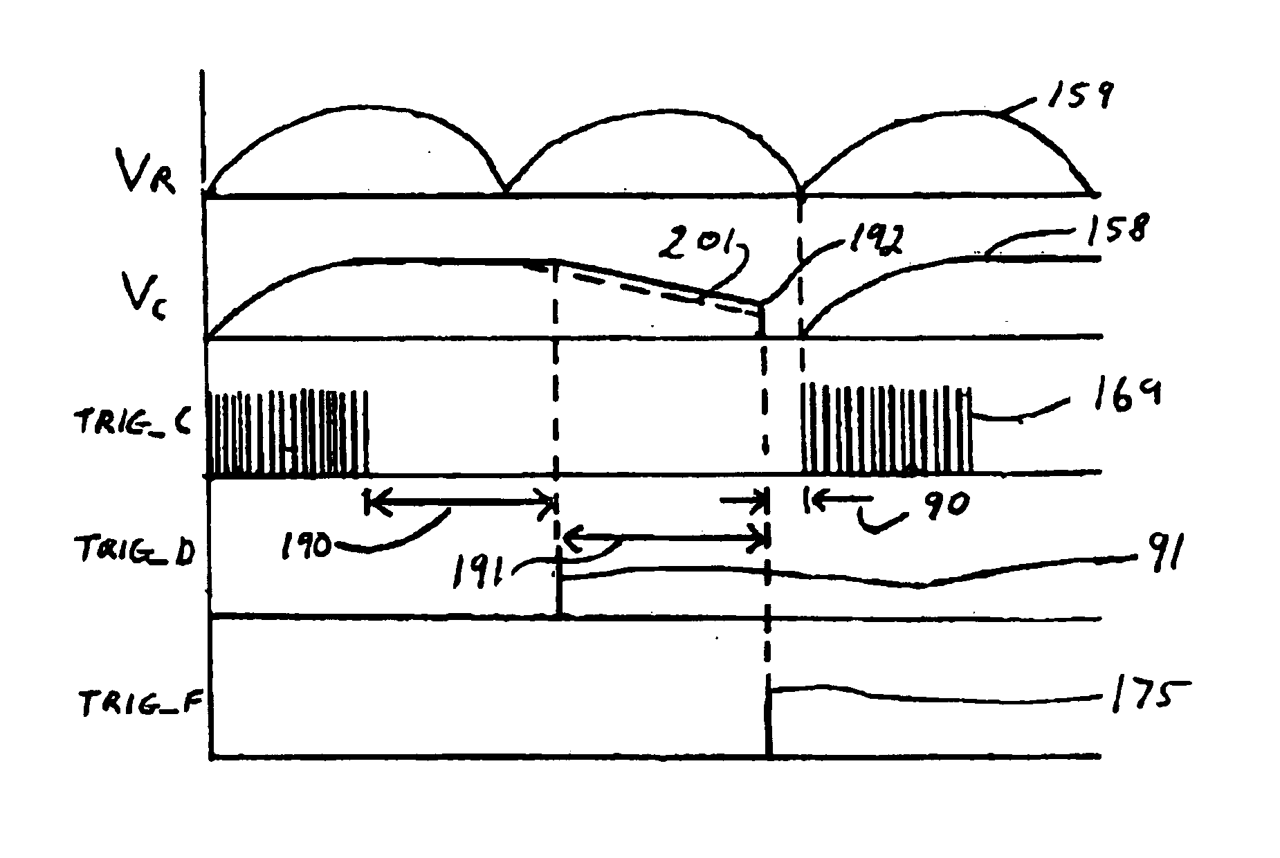
The...


PUM


Abstract

The present invention relates to a camera (102) with strobe flash illumination (116) for capturing an image of an object (6), and to a document scanning system (101) and method of using such a camera (102) to capture an image of a document (6). The camera (102) comprises an image capture means, an objective lens (114) with a field of view (118) to image optical radiation (119) from an object plane (8) onto the image capture means (52), a strobe flash (116) for illuminating the object plane (8), electronic pulse circuitry to pulse the strobe flash (116) at a rate which is sufficiently quick that the illumination appears to a user of the camera (102) to be substantially steady owing to persistence of vision, and a shutter means (104) to synchronize the capture of one or more images by the image capture means, each image being captured with at least one pulse from the strobe flash. The shutter means (104) is adapted to capture images at a rate substantially below the rate at which the strobe flash (16, 116) is pulsed.

Description

BACKGROUND OF THE INVENTIONThe present invention relates to a camera with strobe flash illumination for capturing an image of an object, and to a document scanning system and method of using such a camera to capture an image of a document.In recent years, document scanners have become commonplace. Although these work well and are relatively inexpensive, a document scanner occupies a significant amount of scarce desk space.The use of a camera to take a photograph of a document consisting of text and / or images offers one way of dealing with the problem of wasted desk space. In conventional film or electronic photography, a person may look through a viewfinder to aim the camera at an object. When the object is a document, for example a document lying on a desk in an office illuminated by ambient light from windows and overhead lighting, it will usually be necessary to use an additional source of light, such as a conventional electronic flash synchronised with a mechanical shutter or el...

Claims


Application Information

Patent Timeline
Patent Type & Authority Patents(United States)
IPC IPC(8): G03B15/00G03B15/03G03B15/04H04N5/235G03B7/16G03B15/05G03B17/56G03B19/02H04N5/222H04N5/225H05B41/34
CPCG03B15/00H04N5/2354G03B15/0457H04N23/74
Inventor KAHN, RICHARD OLIVER
Owner HEWLETT PACKARD DEV CO LP
Why Eureka
Try Eureka