Water harvesting device

a water harvesting device and water technology, applied in the field of water harvesting devices, to achieve the effect of enhancing the ability of water extraction, reducing the volume of water, and reducing the spa

Inactive Publication Date: 2010-04-22
MAXTECH CONSUMER PRODS
View PDF6 Cites 16 Cited by
  • Summary
  • Abstract
  • Description
  • Claims
  • Application Information

AI Technical Summary

Benefits of technology

[0013]In one aspect of the present invention, the water harvesting device contains a large water storage area to increase its volume capacity while remaining unobtrusive and visually appealing as it occupies less space adjacent to a building than a traditional rain barrel. The device may provide for an enhanced ability for water extraction and irrigation for the user with the enhanced water pressure.
[0014]The present invention generally comprises a water storage area that is higher in stature than a typical rain barrel. The storage volume may be increased while the breadth of the storage area is minimized to be less obtrusive than the traditional barrel. The reduced breadth of the device also allows it to be used in areas where building may be close together and a traditional rain barrel would not allow enough clearance between the buildings.
[0015]Another aspect of the present invention is the longitudinal height of the unit that allows for increased water elevation, which may further benefit the water removal and irrigation ability of the device as there may be an increase in pressure at the bottom portions of the water storage area.
[0016]With a mere increase in height a traditional water harvesting device may have challenges. The present invention has contemplated this situation and appropriate solutions have been designed as described below. One such feature of the present invention is the inclusion of biasing means allowing for the increased stability of the water storage area by biasing the load of the water harvesting device towards the building to take advantage of the solid building the device resides against. Another such feature is the discrete integration of aesthetic features that add to the strength of the device in needed areas.
[0017]A further aspect of the present invention enables the user to collect a significant amount of rainwater from the roof top collection without the need to install a bulky, traditionally shaped unit. The present invention also provides for an improved water extraction and irrigation capability.
[0018]Another aspect of the present invention is the ability to ship and store the units efficiently. With the sleek and compact design the units are better able to stack saving on wasted space during shipping and storing.

Problems solved by technology

The reduced breadth of the device also allows it to be used in areas where building may be close together and a traditional rain barrel would not allow enough clearance between the buildings.

Method used


Image

  • Water harvesting device
  • Water harvesting device
  • Water harvesting device

Examples


Embodiment Construction

[0027]Turning now descriptively to the drawings, in which the preferred embodiment is shown in the various configurations to describe the invention. It will be understood that while the invention is described with respect to the preferred embodiment the device may be configured differently while achieving the essence of the invention.

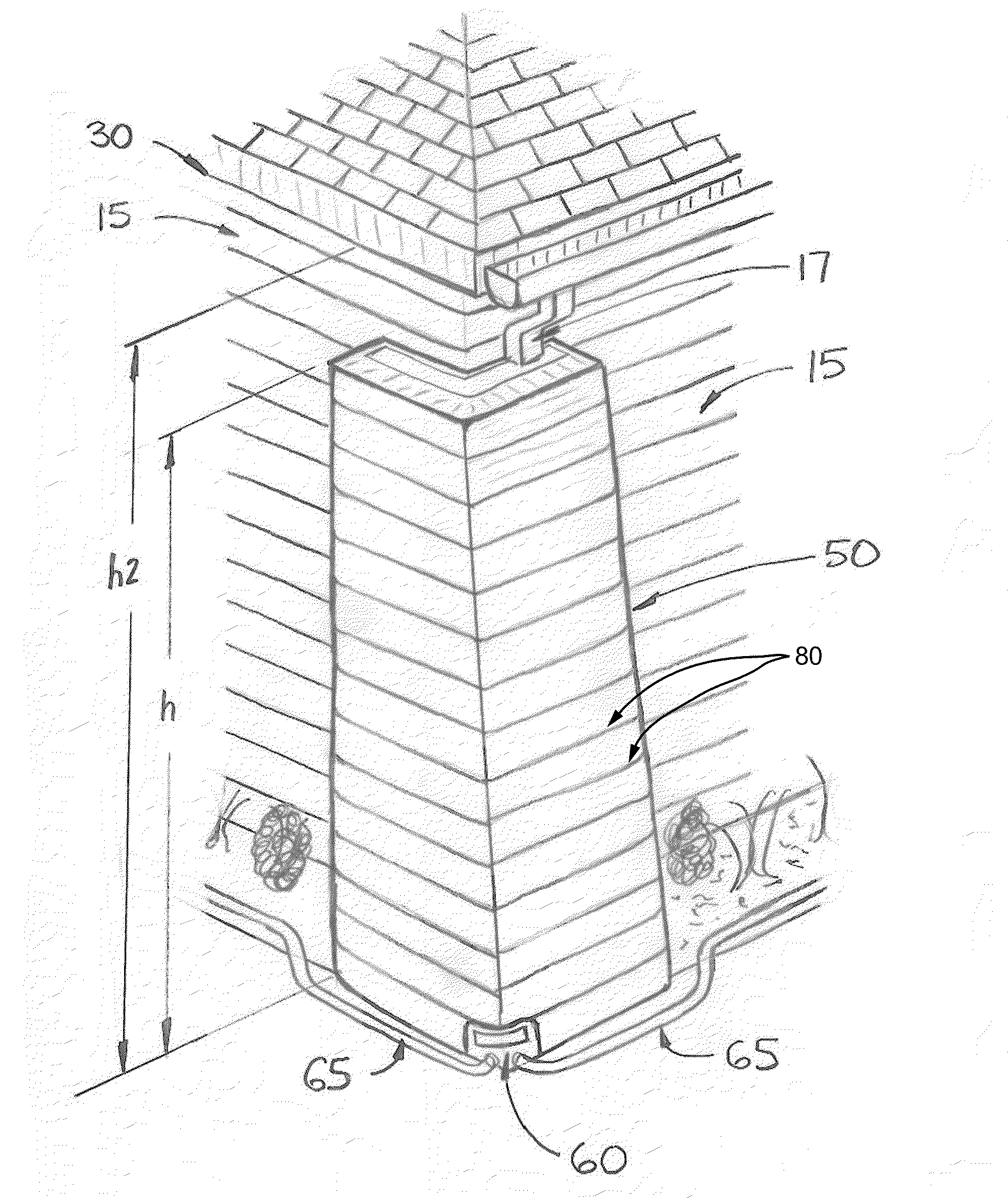
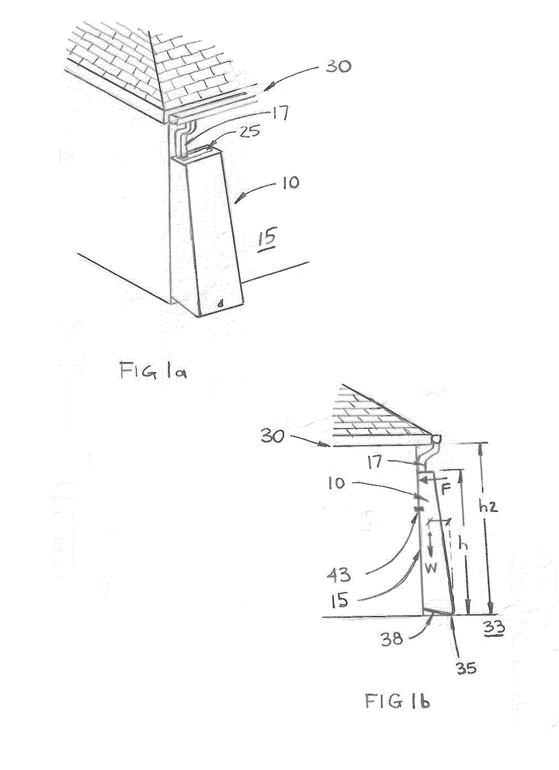
[0028]FIG. 1a illustrates a preferred embodiment of the present invention in an installed position. The water harvesting device 10, defined by a plurality of longitudinal walls, is shown adjacent to a wall 15 of a single level building, an existing structure. The water harvesting device may be located adjacent to any wall that contains a water source such as a downspout 17. The wall 15 is shown with downspout 17 feeding rain water into the device 10 through the water entry opening 25.

[0029]The water harvesting device is shown in FIG. 1a as proportionately tall with respect to the height of the wall 15 and the roof line 30. Ideally to improve the benefit...


PUM


Abstract

A water harvesting device comprising a plurality of longitudinal walls, at least one wall adjacent to a wall of an existing structure; the plurality of walls defining at least one water storage area with a height such that water pressure is enhanced; and the water storage area operatively engaging at least one water source.

Description

REFERENCE TO RELATED APPLICATIONS[0001]This application claims the benefit of U.S. Provisional Patent Application No. 61 / 106,356, filed Oct. 17, 2008, which is incorporated herein by reference.FIELD OF THE INVENTION[0002]The present invention relates generally to water harvesting devices commonly referred to as rain barrels. More particularly, the present invention relates to such devices for use in residential, multi-residential and commercial applications.BACKGROUND OF THE INVENTION[0003]It can be appreciated that water harvesting devices or rain barrels have been around for years. The purpose of these devices is quite simple: capturing and storing water for subsequent use. Commonly these devices have collected rainwater from water sources as an eaves and downspout system and provide the ability to disperse the water when needed.[0004]With the growing concern regarding water consumption and in an effort to reuse more natural resources one environmentally friendly solution has been...

Claims


Application Information

Patent Timeline
Patent Type & Authority Applications(United States)
IPC IPC(8): B65D90/02
CPCE03B3/03Y02A20/108Y02A20/00
Inventor ALLAN, SCOTT W.
Owner MAXTECH CONSUMER PRODS
Why Eureka
Try Eureka