
Method and device for initiating and executing a deceleration of a vehicle

a vehicle and deceleration technology, applied in the direction of vehicles, pedestrian/occupant safety arrangements, vehicle position/course/altitude control, etc., can solve the problems of injury risk, collision risk and injury risk, and the probability of collision of vehicles, so as to reduce the computing capacity necessary for determining the movement trajectories and increase the system performance

Inactive Publication Date: 2005-02-15
ROBERT BOSCH GMBH
View PDF9 Cites 45 Cited by
  • Summary
  • Abstract
  • Description
  • Claims
  • Application Information

AI Technical Summary

Benefits of technology

Furthermore, it may be advantageous for determining the movement trajectories if a characteristic vehicle dynamics model is stored for each object class, with the aid of which the family of possible movement trajectories to be predicted may be determined with higher precision.
Furthermore, it may be advantageous if, for the precalculation of the movement trajectories of the particular vehicle and the objects detected, only those trajectories are taken into consideration in which the forces arising on the wheels of the vehicle due to a combination of steering and braking interventions are not greater than the maximum force which may be transmitted from the wheel onto the roadway. By eliminating those movement trajectories in which steering and braking forces arise which may not be transmitted from the wheel onto the roadway, the computing capacity necessary for determining the movement trajectories may be reduced and the performance of the system may thus be increased.

Problems solved by technology

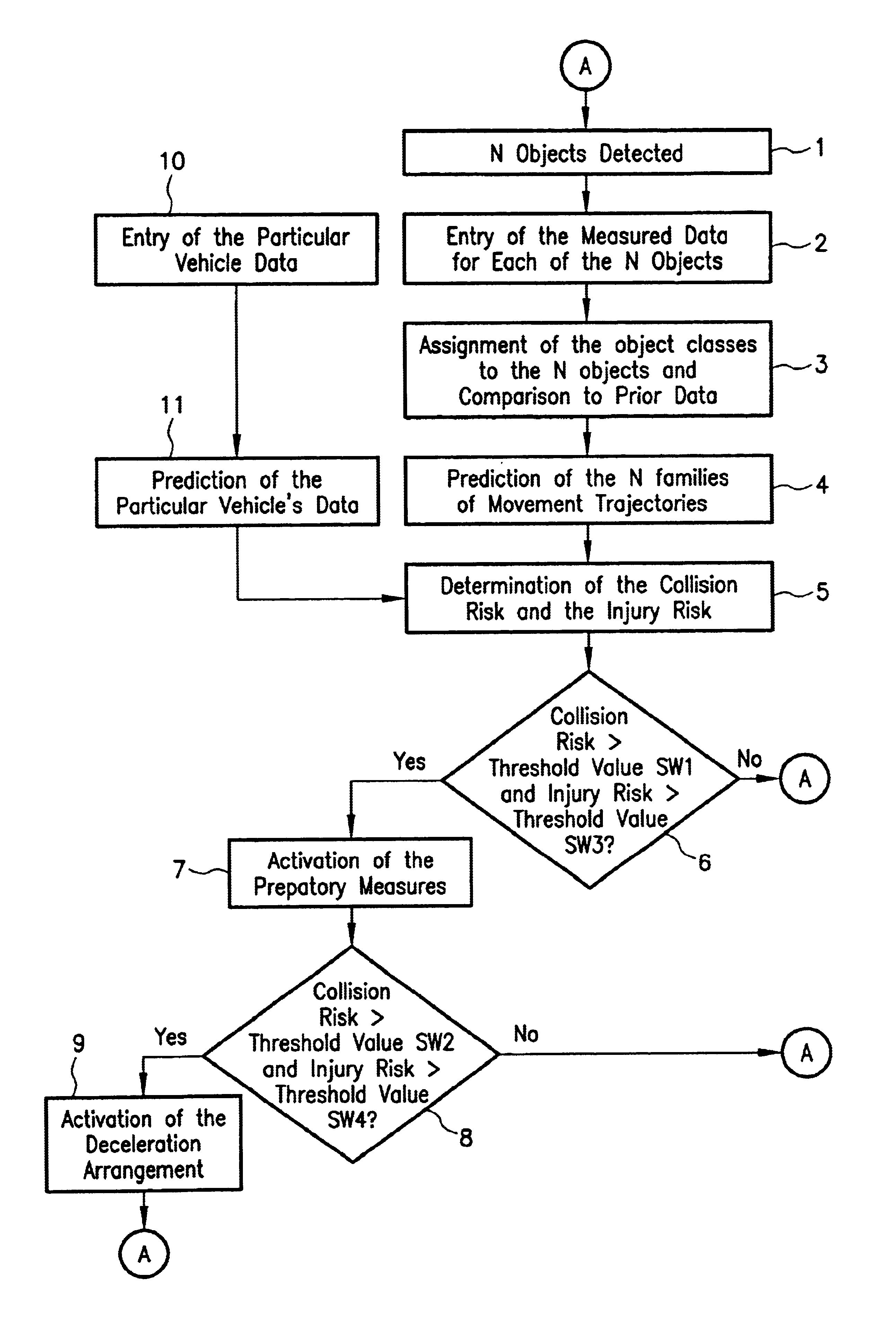
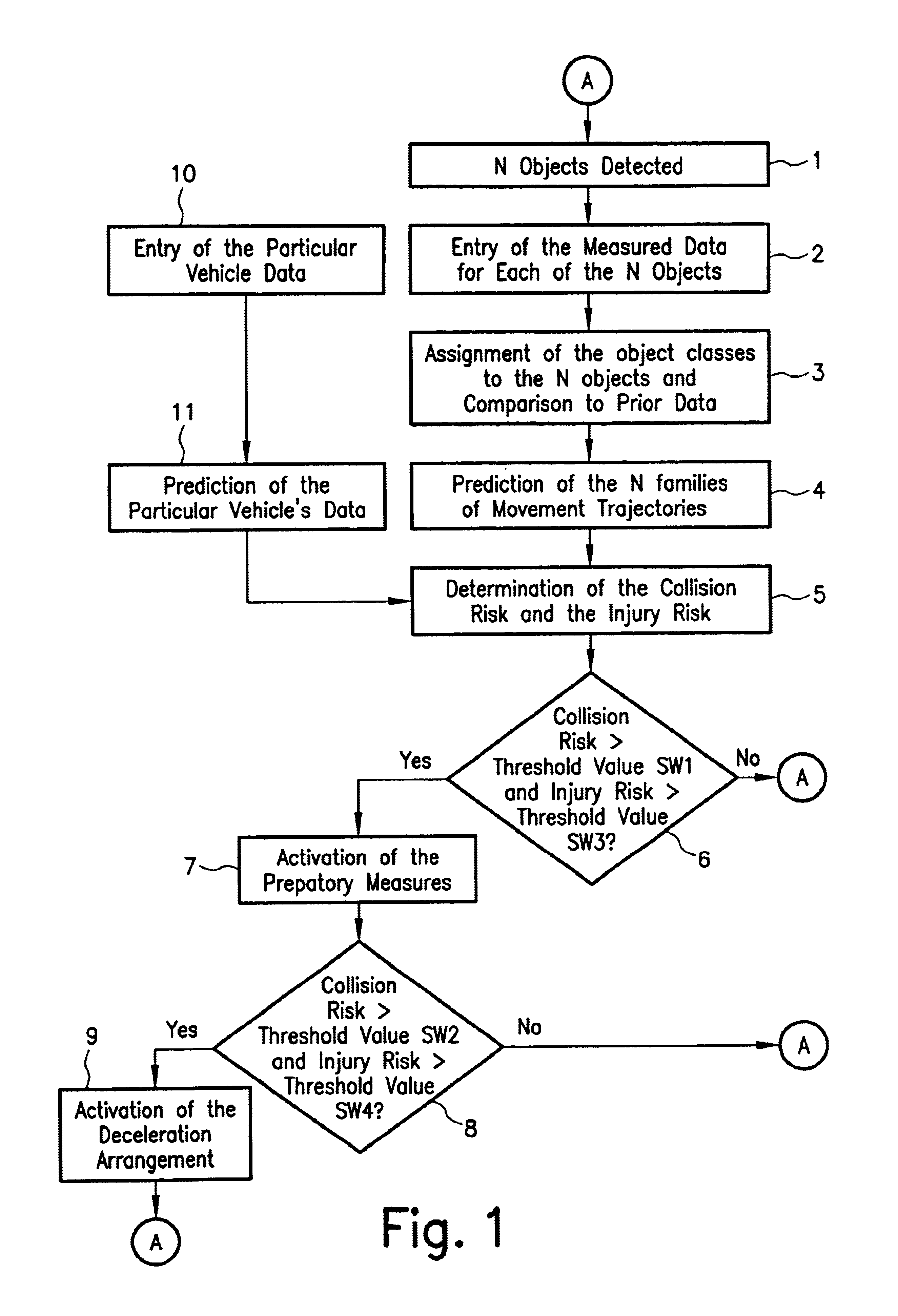
Furthermore, a collision risk and an injury risk are determined using the object class detected and the movement trajectories determined, as a function of which the deceleration devices of the vehicle may be activated.
The collision risk indicates the probability that the vehicle will collide with an object.
The injury risk, in contrast, estimates the risk to the occupants of the vehicle due to this possible collision.
In the case in which the side mirrors of two vehicles will unavoidably touch as they drive by one another, there is a high collision risk, but only a low injury risk, so that automatic triggering of deceleration is not to be implemented.

Method used


Image

  • Method and device for initiating and executing a deceleration of a vehicle
  • Method and device for initiating and executing a deceleration of a vehicle
  • Method and device for initiating and executing a deceleration of a vehicle

Examples


Embodiment Construction

FIG. 1 shows a flow chart of an example embodiment of the method according to the present invention. This flow chart represents an endless loop and is continuously repeated. In block 1, the environmental sensor system, in the form of a radar, lidar, or video sensor, determines how many objects lie in the detection range of the sensor. These n detected objects are stored in the memory. In block 2 of the flow chart, the measurement data is entered for each of the n objects. In this case, this data includes various variables which are provided directly from the environmental sensor system. The measured variables may be one or more of the following variables: relative speed of the object to the particular vehicle, distance of the object, horizontal dimension of the object, vertical dimension of the object, geometry of the object, and surface composition of the reflecting surface. These measured data at point in time t+Δt are compared to the measured data of the preceding measurement cyc...


PUM


Abstract

A method and a device for triggering and implementing a deceleration of a vehicle to avoid a collision, in which, using a device for adaptive cruise control, objects in the sensor detection range are detected and measured variables are determined for each detected object. The detected objects are assigned to various object classes on the basis of the determined, associated measured variables, and the movement trajectories of the objects are predicted on the basis of the assignment of the detected objects to the particular class. Furthermore, a collision risk and an injury risk are determined from these predicted movement trajectories of the objects and the associated, detected object classes. In the event of the existence of preselected combinations of collision risks and injury risks, the deceleration devices of the vehicle are activated as a function of the degree of the collision risk.

Description

FIELD OF THE INVENTIONA method and a device triggers and implements a deceleration of a vehicle to avoid a collision and / or reduce the severity of an accident. Using at least one radar, lidar, or video sensor, or a combination thereof, objects in the sensor detection range are detected and measured variables are determined for each detected object. The detected objects are assigned to various object classes on the basis of the determined, associated measured variables, and the movement trajectories of the objects are predicted on the basis of the assignment of the detected objects to the particular class. A collision risk and an injury risk are determined from these predicted movement trajectories of the objects and their associated, detected object classes and, in the event of the existence of preselected combinations of collision risks and injury risks, the deceleration devices of the vehicle are appropriately activated.BACKGROUND INFORMATIONConventional systems for adaptive cruis...

Claims


Application Information

Patent Timeline
IPC IPC(8): B60K31/00B60R21/01B60T7/22B60T7/12B60R21/013B60R21/0134B60W10/18B60W30/08B60W30/16
CPCB60K31/0008B60T7/22B60W10/18B60W10/20B60W30/08B60W30/16B60R21/013Y02T10/84B60R21/0134B60R2021/01259B60R2021/01311B60T2201/022B60T2201/12B60W30/09B60W2550/20G08G1/164G08G1/166B60W2554/00B60W2554/804B60W2554/802
Inventor WINNER, HERMANNHEINEBRODT, MARTINWILHELM, ULFKNOOP, MICHAELBRAEUCHLE, GOETZWEILKES, MICHAELUHLER, WERNERHERMSEN, WOLFGANGTHIELE, JOACHIMSTAEMPLE, MARTINOECHSLE, FRED
Owner ROBERT BOSCH GMBH
Learn More