Fluid metering device

Inactive Publication Date: 2005-02-22
ROPER PUMP CO LLC
View PDF12 Cites 25 Cited by
  • Summary
  • Abstract
  • Description
  • Claims
  • Application Information

AI Technical Summary

Benefits of technology

In a preferred embodiment of the invention, the first liquid discharge port and the second liquid inlet port are preferably positioned on opposite sides of an intermeshing portion of the first and second gears. In this embodiment of the invention, the first and second liquid inlet ports are configured so that liquid passing through the first liquid inlet port exerts a first force on the second gear in a first direction, and so that liquid passing through the second liquid inlet port exerts a second force on the second gear in a second direction, the second direction being substantially opposite to the first direction. This serves to reduce bearing loads associated with the second gear.

Problems solved by technology

Such prior art liquid flow dividers have significant disadvantages.
First, because it is necessary to include a separate dividing unit for each discharge stream, these liquid flow dividers tend to be mechanically complex.
As a result, the flow dividers tend to be expensive to produce and maintain.
Also, because the drive trains within these flow dividers are typically less robust than the other components within the flow dividers, the drive trains often break or otherwise malfunction.
However, because only a limited number of planetary gears may be positioned around each central gear, such flow dividers typically include an extended array of dividing units that are linked together, or “stacked”, via a drive train as discussed above.
Accordingly, like the Kiernan two-gear flow divider, these planetary flow dividers tend to be mechanically complex, which causes the flow dividers to be expensive to produce and maintain.
Also, because the drive trains within these flow dividers are typically less robust than the flow divider's other components, the drive trains often break or otherwise malfunction.
A further disadvantage of both the Kiernan and Scherzinger flow dividers is that the design of these flow dividers tends to result in substantial bearing loads being exerted on the bearings that support the flow dividers' various gears.
This can result in premature failure of the bearings within the flow dividers.

Method used


Image

  • Fluid metering device
  • Fluid metering device
  • Fluid metering device

Examples


Embodiment Construction

The present invention will now be described with reference to the accompanying drawings, in which preferred embodiments of the invention are shown. This invention may, however, be embodied in many different forms and should not be construed as limited to the embodiments set forth below. Rather, these embodiments are provided so that this disclosure will be thorough and complete, and will fully convey the scope of the invention to those skilled in the art. Like numbers refer to like elements throughout.

Definitions

For the purposes of this disclosure, the following terms have the meanings set forth below:

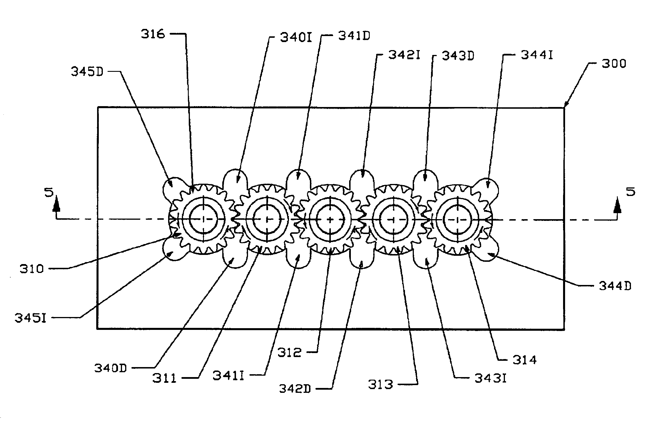
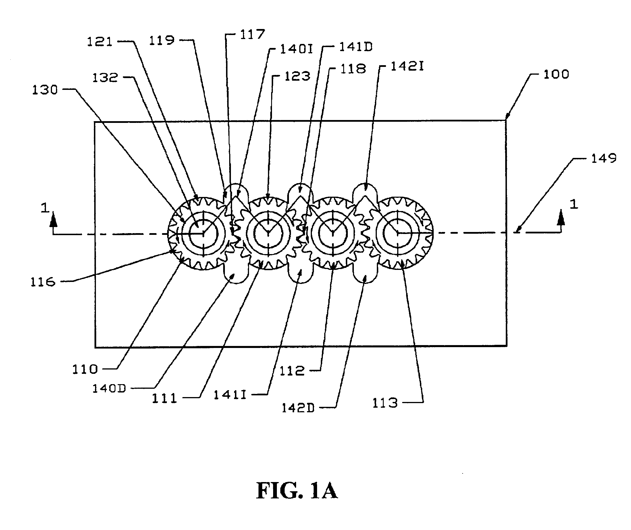
A “series of gears” is a plurality of gears that are positioned so that the gear teeth of each gear within the series of gears intermeshes with the gear teeth of at least one other gear in the series.

An “intermeshing portion” of a pair of neighboring gears is the location at which the teeth of the first gear in the pair comes into contact with the teeth of the second gear in the pair.

A...


PUM


Abstract

A fluid metering device that preferably includes a substantially linear series of intermeshing gears. The fluid metering device includes an inlet port adjacent the intermeshing portion of each pair of gears within the series adjacent the point at which the pair of gears diverge. The device further includes an discharge port adjacent the intermeshing portion of each pair of gears within the series adjacent the point at which the pair of gears converge. The device is configured to convey liquid from a main inlet stream of liquid, through the inlet ports, and out the discharge ports at substantially equal rates. The device preferably includes a pressure balance inlet port and a pressure balance discharge port adjacent the exterior portion of each end gear within the series of gears for balancing forces exerted on the end gear by liquid passing through the various inlet and discharge ports.

Description

FIELD OF THE INVENTIONThis invention relates generally to devices for regulating the flow of liquids, and particularly relates to a flow divider for evenly dividing a stream of liquid, such as liquid fuel, into two or more smaller streams of liquid.BACKGROUND OF THE INVENTIONWhen working with liquids, it is often desirable to divide a single stream of liquid into several smaller, equal streams of liquid. This is typically done using a fluid metering device such as liquid flow divider, an equal-flow pump, or an equal-flow liquid motor.A typical prior art liquid flow divider is taught in U.S. Pat. No. 4,531,535 to Kiernan (“Kiernan”). As shown in FIG. 4 of Kiernan, such liquid flow dividers typically include multiple dividing units of two intermeshed spur gears. The various dividing units are typically linked together by a drive train that may include a drive line, drive shafts, or a sun gear. As a result of this linkage, all of the gears within the various dividing units rotate at su...

Claims


Application Information

Patent Timeline
IPC IPC(8): G05D11/00F02C7/228F04C2/18F04C11/00F04C15/00
CPCF02C7/228F04C2/18G05D11/006F04C15/0042G05D11/003F04C11/001Y10T137/2516Y10T137/2524Y10T137/0363Y10T137/85938
Inventor FLAVELLE, WILLIAM D.
Owner ROPER PUMP CO LLC
Why Eureka
Try Eureka