Joining structure

a jointing structure and joint technology, applied in the direction of couplings, rod connections, machine supports, etc., can solve the problems of deteriorating proof stress and fatigue properties, affecting the performance of the structure, and affecting the strength of the jointing structure, so as to achieve the effect of reducing the stress concentration near the end(s) reducing the rigidity at one or both ends of the tabular member, and reducing the stress concentration

Inactive Publication Date: 2005-02-22
NIPPON STEEL CORP +2
View PDF33 Cites 75 Cited by
  • Summary
  • Abstract
  • Description
  • Claims
  • Application Information

AI Technical Summary

Benefits of technology

As described above, in the present invention, the rigidity at one or both ends of a tabular member decreases by bending the end(s) (toe(s)) of the tabular member such as a reinforcing rib, etc., preferably, in a direction deviating from the direction of the principal stress of a structural member. As a result, when a load is applied on the structural member, the stress concentration near the end(s

Problems solved by technology

In a conventional joining structure as described above, however, there is a problem that, when a bending moment is applied on the structural member 10, a large out-of-plane bending stress concentrates at the portions of the structural member 10 near the toes of the reinforcing ribs 12 and, as a consequence, the performance of the structure is deteriorated.
Another problem is that, when the re

Method used


Image

  • Joining structure
  • Joining structure
  • Joining structure

Examples


example

A fatigue strength test was carried out for the purpose of confirming the effect of the present invention described above.

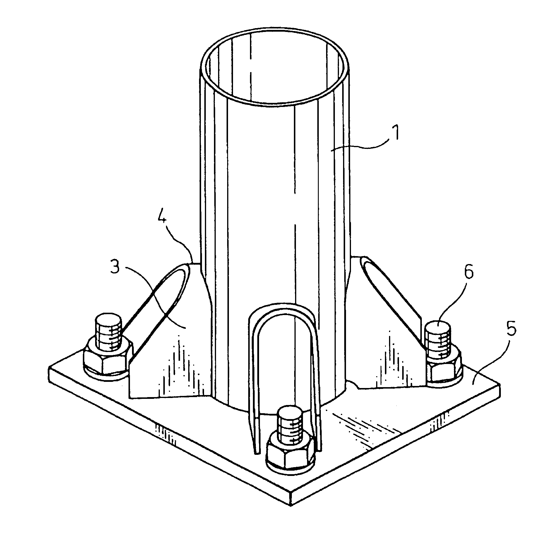
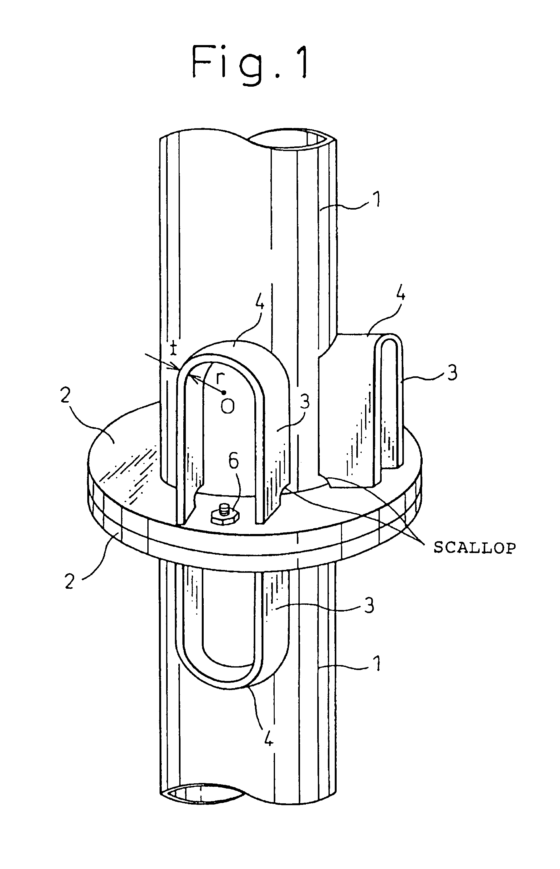
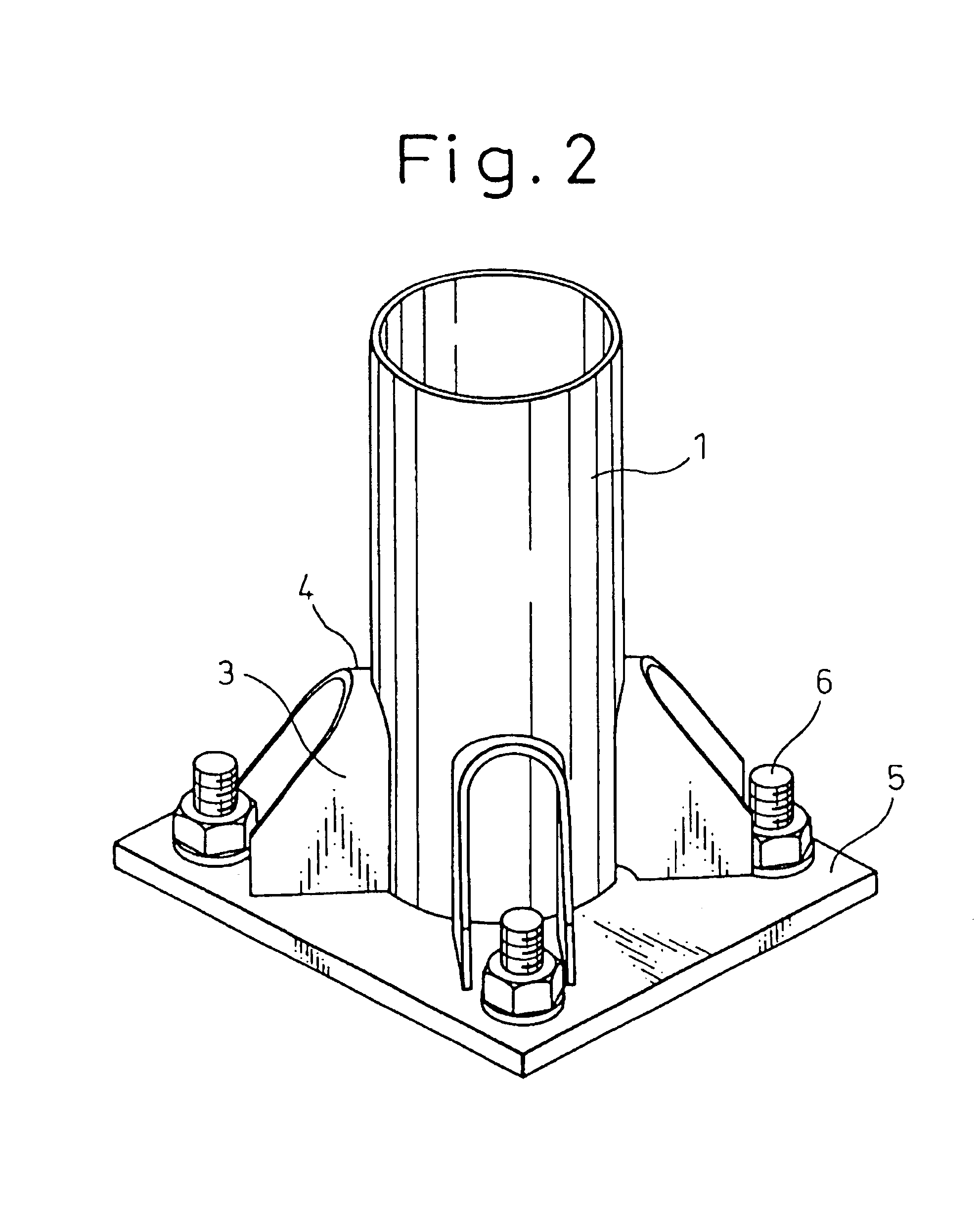
Two kinds of test pieces, one according to a conventional technology and the other to the present invention, were prepared for the test. The test pieces according to the conventional technology were structured as shown in FIG. 22, wherein a steel pipe 1 m in length was fixed upright onto a base plate 22 mm in thickness and its base portion was reinforced with conventional vertical ribs. The test pieces according to the present invention were structured as shown in FIG. 2, wherein a steel pipe 1 m in length was fixed upright onto a base plate 22 mm in thickness and its base portion was reinforced with U-shaped reinforcing ribs. Co2 gas shielded arc welding was employed for all the welding work, and the steel grade of all the steel sheets used for the test was Japanese Industrial Standard SM400.

The fatigue strength of each test piece under a bending load imposed on...


PUM


Abstract

The present invention provides a joining structure capable of greatly improving the proof stress and the fatigue property by alleviating the stress concentration and residual stress caused by welding heat at one or both ends of a tabular member.
In the present invention, one or both ends 4 of a tabular member 3 such as a reinforcing rib, fixed to the surface of a structural member 1 in the direction of the principal stress of the structural member 1 so as to protrude in the shape of T, is/are bent in a direction deviating from the direction of the principal stress and, by this, the rigidity at the end(s) 4 of the tabular member 3 decreases and the stress concentration is alleviated. It is preferable to bend one or both ends of a tabular member 3 in the shape of an gradual curve and to the extent that each bent end is formed at a right angle to the direction of the principal stress. The tabular member may have the shape of a flat plate, or it may be bent so that it has the shape of U or V as a whole. Further, the tabular member may be welded to a structural member or formed as an integral part of a structural member.

Description

TECHNICAL FIELDThe present invention relates to a joining structure constructed by attaching one or more tabular members, such as reinforcing ribs, etc. or anchor bolts, to a structural member which takes various forms.BACKGROUND ARTA joining structure, as shown in FIG. 22 or 23, has been conventionally used for a join, for instance, between a steel base structure and a foundation. The conventional joining structure is formed by welding a bolt connection base plate 11 to an end of a structural member 10 and reinforcing the joining structure with reinforcing ribs 12 attached between the structural member 10 and the base plate 11. The reinforcing ribs 12 are tabular members extending in the direction of the principal stress of the structural member 10 and are attached to protrude from the surface of the structural member 10 in the shape of a T.In a conventional joining structure as described above, however, there is a problem that, when a bending moment is applied on the structural me...

Claims


Application Information

Patent Timeline
IPC IPC(8): E04B1/24E04H12/22E04B1/58
CPCE04B1/2403E04H12/2261E04B2001/2415E04B2001/2445E04B2001/2448E04B2001/2451E04B2001/2457Y10T403/46E04B2001/2463Y10S248/903Y10T403/27Y10T403/64Y10T403/28E04B2001/246F16B2200/50
Inventor SUGIMOTO, MASAKAZUOKIMOTO, MASAYUKIKONDO, TETSUMIKITA, SHIROHIGASA, MASAFUMI
Owner NIPPON STEEL CORP
Why Eureka
Try Eureka