Variable venturi

a variable venturi technology, applied in the field of jet powered watercraft, can solve problems such as drawbacks of conventional variable venturis, and achieve the effect of reducing the cross-sectional area of the discharge opening

a variable venturi technology, applied in the field of jet powered watercraft, can solve problems such as drawbacks of conventional variable venturis, and achieve the effect of reducing the cross-sectional area of the discharge opening

US6857920B2Inactive Publication Date: 2005-02-22BOMBARDIER RECREATIONAL PROD INC

Image

  • Variable venturi
  • Variable venturi
  • Variable venturi

Examples


Embodiment Construction

Embodiments of the present invention are described with reference to a PWC for purposes of illustration only. It is to be understood that the jet propulsion systems and variable venturis described herein can be utilized in any watercraft. For example, the jet propulsion systems disclosed herein may also be useful in small boats or other floatation devices other than those defined as personal watercrafts. Simply stated, the variable venturis described herein may be used with any type of jet propulsion system.

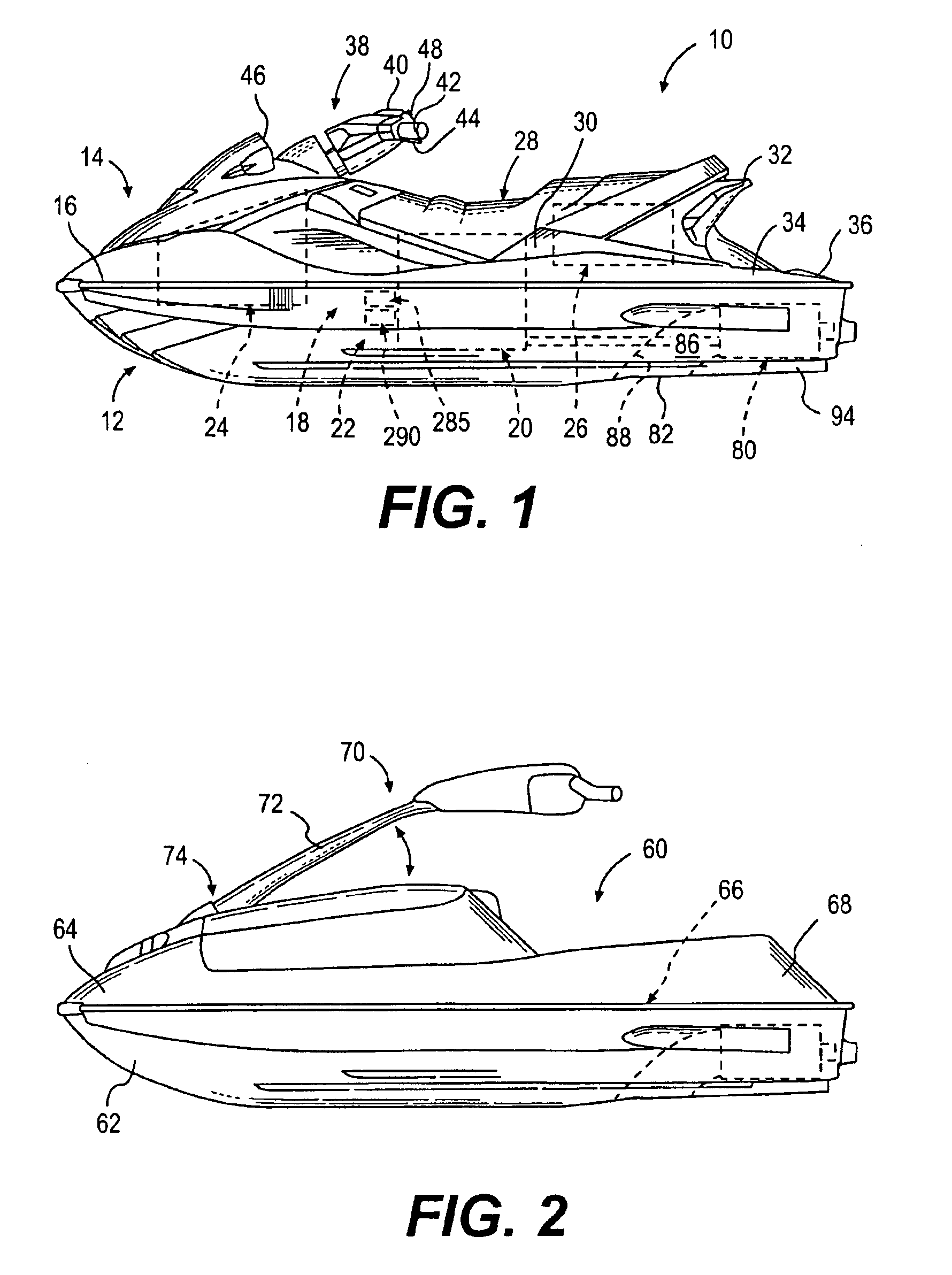
The general construction of a personal watercraft 10 in accordance with a preferred embodiment of this invention is shown in FIG. 1. The following description relates to one way of manufacturing a PWC according to a preferred design. Obviously, those of ordinary skill in the watercraft art will recognize that there are other known ways of manufacturing and designing watercraft and that this invention encompasses other known ways and designs.

As illustrated in FIG. 1, the watercraf...


PUM


Abstract

Variable venturi for use in jet propulsion systems of watercraft include discharge openings with selectively variable discharge areas that enable a venturi controller to selectively maximize top speed, acceleration, and / or fuel efficiency. The variable venturi may include a plurality of circumferentially-spaced, squeezable, flexible sections that selectively move radially inwardly to alter the discharge area. Alternatively, the variable venturi may include a flexible venturi with a variably-shaped flexible discharge opening. Alternatively, the variable venturi may include a main rear discharge opening and a plurality of additional discharge openings with selectively openable valves, whereby selective opening of the valves effectively increases the discharge area. Alternatively, the variable venturi may have a movable end flap that selectively varies the discharge area.

Description

BACKGROUND OF THE INVENTION1. Field of the InventionThis invention relates to jet powered watercraft, especially personal watercraft (“PWCs”). More specifically, the invention concerns the jet propulsion system of the watercraft. In particular, the invention is directed to controlling thrust.2. Description of Related ArtJet powered watercraft have become very popular in recent years for recreational use and for use as transportation in coastal communities. The jet power offers high performance, which improves acceleration, handling and shallow water operation. Accordingly, PWCs and jet boats, which typically employ jet propulsion, have become common place, especially in resort areas. As use of PWCs and jet boats has increased, operators expect better performance, including greater operational efficiency, higher top speed, faster acceleration, and improved control.FIG. 12 illustrates a prior art jet propulsion system 600 disposed within a hull 612 of a watercraft, of which only a por...

Claims


Application Information

Patent Timeline
22 Feb 2005
Publication
US6857920B2
IPC
B63H11/00; B63H11/10
CPC
B63H11/10; Y02T70/56; Y02T70/50
Inventors
MARATHE, BHASKAR; PESANT, GILLES