Electronic endoscope system including a plurality of video-processors

a video-processor and electronic technology, applied in the field of electronic endoscopes, can solve the problems of complex assembly high cost of electronic endoscope systems, and large space for setting, so as to reduce costs, reduce setup space, and lift diagnostic efficiency

Inactive Publication Date: 2005-02-22
ASAHI KOGAKU KOGYO KK
View PDF9 Cites 55 Cited by
  • Summary
  • Abstract
  • Description
  • Claims
  • Application Information

AI Technical Summary

Benefits of technology

Therefore, an object of the present invention is to provide an electronic endoscope system, which needs only a small setup space, reduces costs and lifts a diagnostic efficiency.

Problems solved by technology

However, since a plurality of video-processors, monitors and keyboards are needed, the cost of the electronic endoscope system is high and a large space for setting up the electronic endoscope system should is needed.
Further, assembly of the electronic endoscope system becomes complicated, the operator must operate various apparatus, each of which is different in operation.
In consequence, a problem may occur whereby the efficiency of the diagnosis decreases.

Method used


Image

  • Electronic endoscope system including a plurality of video-processors
  • Electronic endoscope system including a plurality of video-processors
  • Electronic endoscope system including a plurality of video-processors

Examples


first embodiment

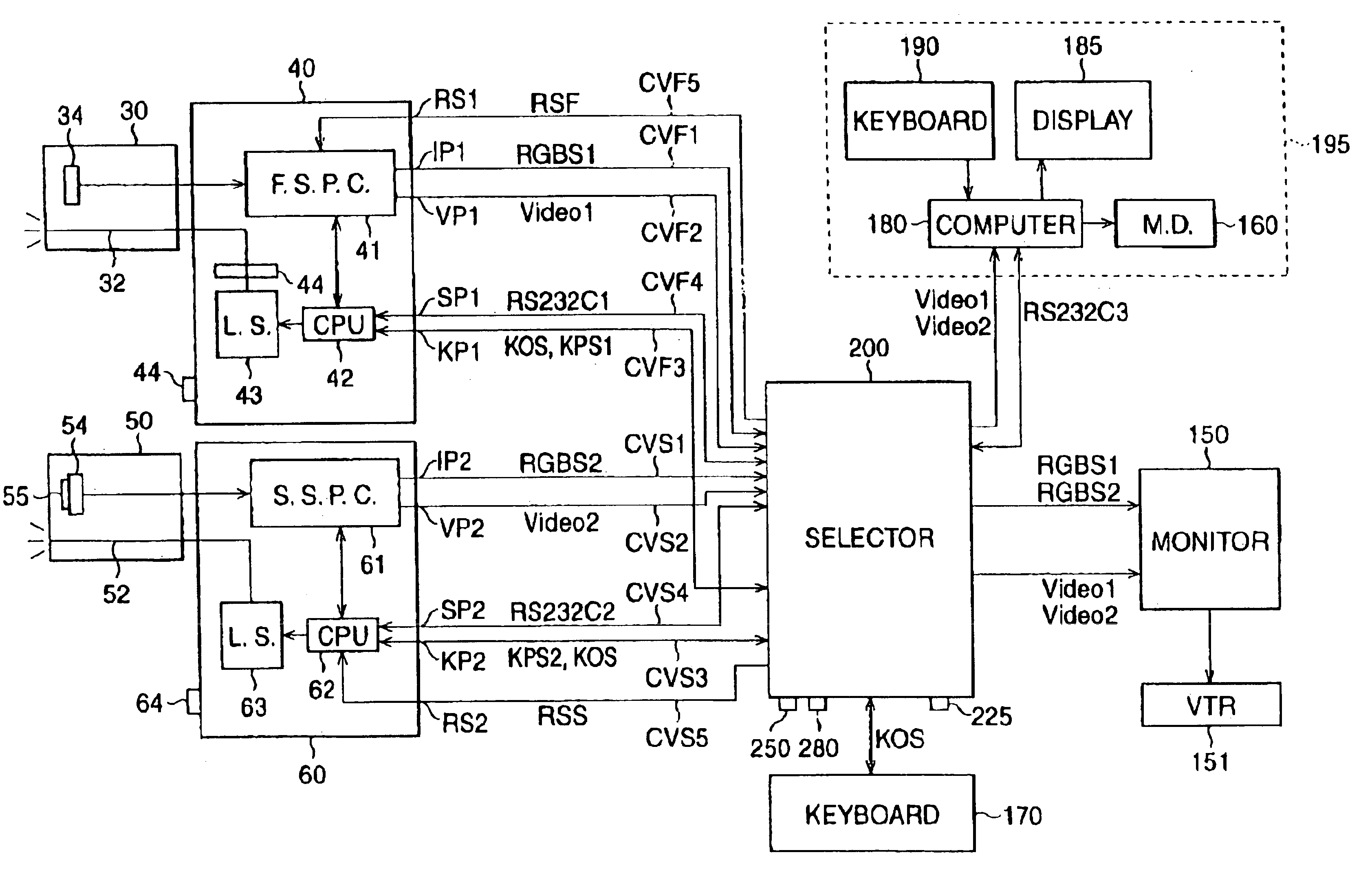
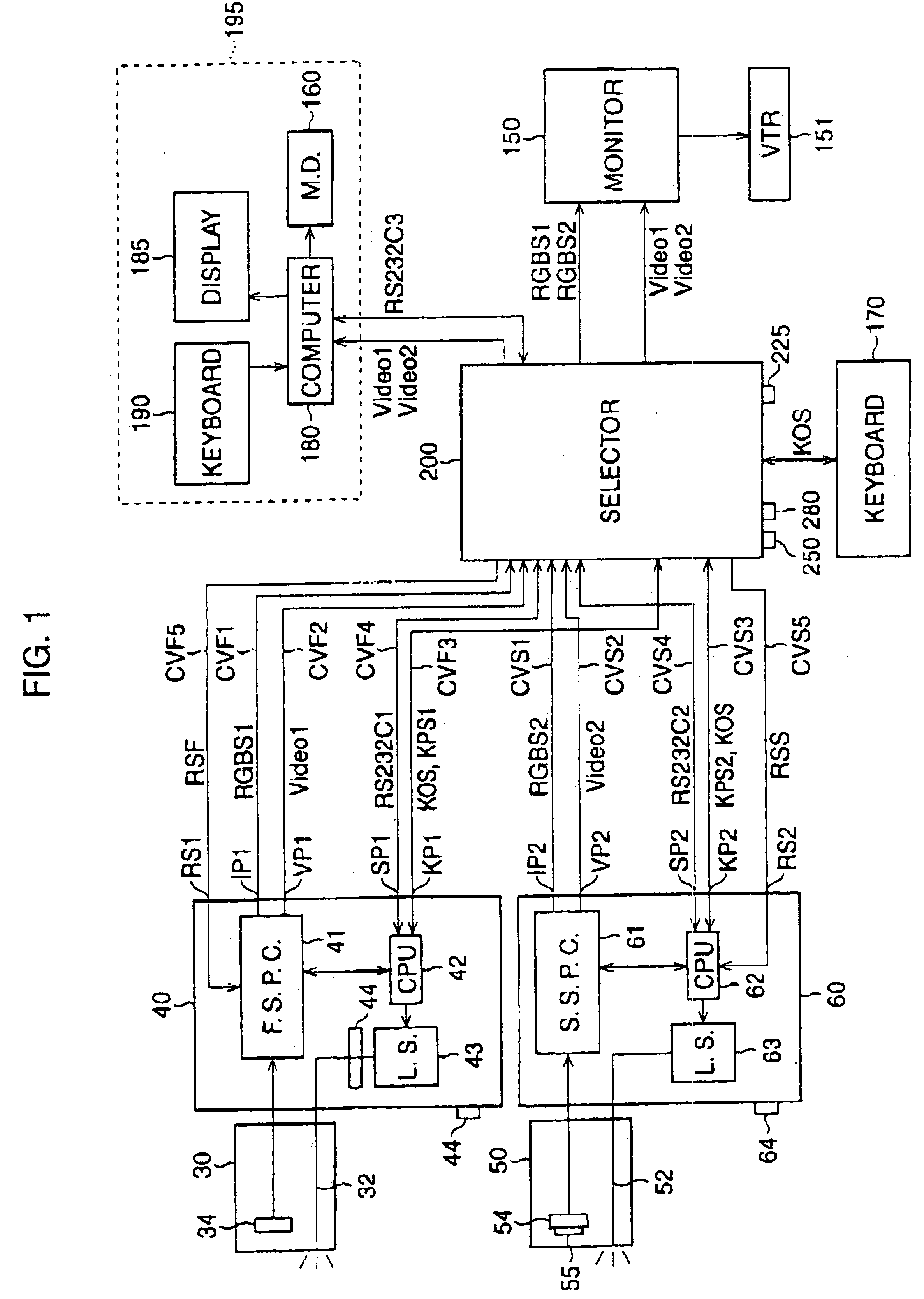
FIG. 1 is a block diagram of an electronic endoscope system of the

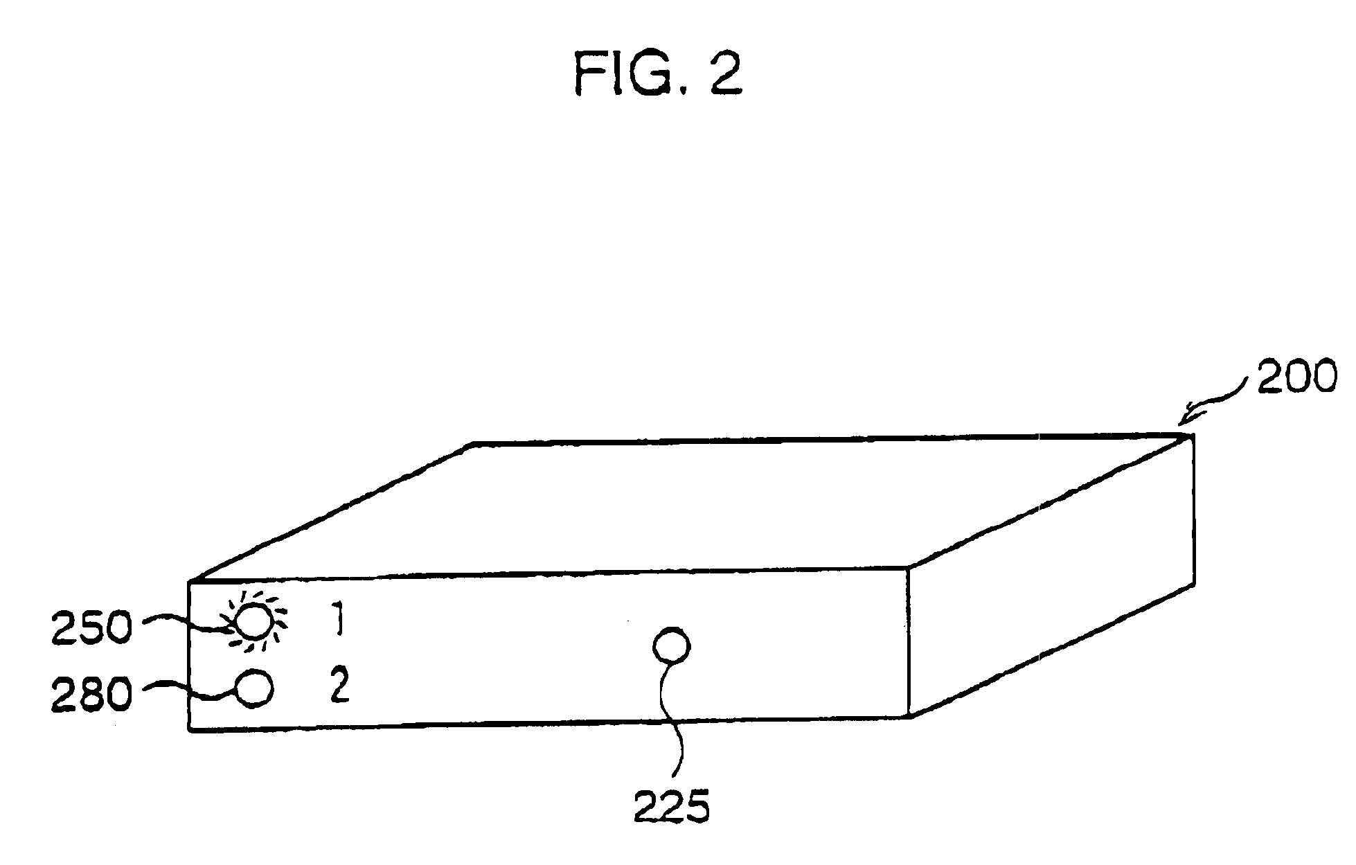
The electronic endoscope system has a first video-processor 40, a second video-processor 60, a first video-scope 30, a second video-scope 50, a selector 200, a keyboard 170, TV monitor 150 and a computer system 195. The first and second video-scopes 30, 50 are detachably connected to the first and second video-processors 40, 60 respectively, and the first and second video-processors 40, 60 are connected to the selector 200. The selector 200 is connected to the monitor 150, the keyboard 170 and the computer system 195. The first video-processor 40 and the second video-processor 60 turn ON by operating power switches 44, 64, respectively.

For a color photographing process at the first video-scope 30 and the first video-processor 40, the R (Red), G (Green), B (Blue) sequential method is applied. A light source 43 radiating white color light, such as a Halogen lamp, and a rotating filter 44 are provided in the first video-...

second embodiment

The second embodiment is different from the first embodiment in that an indicator for indicating the selected video-processor is provided on the keyboard and a setting switch for setting of types of video-processors is provided. Since the reminder of the second embodiment is similar to that of the first embodiment, designations remain the same.

FIG. 11 is a block diagram of the electronic endoscope system including a selector 200′ and a keyboard 170′ of the second embodiment. A setting switch 241 provided on the selector 200′ is a switch for registering the type of video-processor. As described later, the type of video-processor is set by operating the setting switch 241. In the keyboard 170′, a keyboard indicator 300 for indicating the selected video-processor is provided. The keyboard indicator 300 is connected to the selector 200′ via an indicating circuit cable CVK.

FIG. 12 is a block diagram of the selector 200′.

The selector 200′ has a video-processor detecting circuit 242, conne...


PUM


Abstract

An electronic endoscope system has a plurality of video-processors, a plurality of video-scopes, a selector, a monitor and an input device. The plurality of video-processors, the monitor and the input device are connected to the selector. Each of the plurality of video-processors processes image signals from the corresponding video-scope to obtain and output video signals to the selector. The selector selects one of the plurality of video-processors and feeds video signals from a selected video-processor to the monitor. The input device operates the selected video-processor.

Description

BACKGROUND OF THE INVENTION1. Field of the InventionThe present invention relates to an electronic endoscope, which includes a video-scope having an image sensor for photographing an observed area of internal organs and a video-processor for processing image signals read from the image sensor, to which the video-scope is connected. In particular, the present invention relates to an electronic endoscope system using a plurality of video-processors.2. Description of the Related ArtIn the electronic endoscope system, a video-scope has an image sensor and a light guide (fiber-optic bundle) for transmitting light and the video-scope is detachably connected to a video-processor. When an inspection or an operation is executed, the video-scope is inserted into the body cavity. Light, radiating from a light source provided in the video-processor, passes through the light guide and radiates from the distal end of the video-scope, thus the observed area is illuminated. An object image is forme...

Claims


Application Information

Patent Timeline
Patent Type & Authority Patents(United States)
IPC IPC(8): G02B23/24H04N7/18A61B1/04
CPCH04N7/181G02B23/2484A61B1/04
Inventor OZAWA, RYOKOIKE, MAKOTOKOBAYASHI, HIROYUKIIKETANI, KOHEISUGIMOTO, HIDEO
Owner ASAHI KOGAKU KOGYO KK
Why Eureka
Try Eureka