
Stator for a synchronous machine

a stator and synchronous machine technology, applied in the direction of dynamo-electric machines, electrical apparatus, magnetic circuit shapes/forms/construction, etc., can solve the problem that the technique cannot achieve a high copper fill factor, and achieve the effect of sufficiently large phase shift, high slot fill factor, and enhanced magnetic efficiency

Inactive Publication Date: 2005-02-22
SIEMENS AG
View PDF7 Cites 25 Cited by
  • Summary
  • Abstract
  • Description
  • Claims
  • Application Information

AI Technical Summary

Benefits of technology

The laminated armature advantageously provides not only a high slot fill factor, but also a uniform stator yoke height, since the required pass fit in the region of the tooth heads and slot surfaces can be punched out.
Advantageously, the number of pole heads can be identical to the number of pole teeth. The pole heads not only enhance the magnetic efficiency, but also provide a sufficiently large phase shift required for harmonic machines.
Advantageously, a single plate of the yoke armature and a single plate of the star armature can be punched out of a single plate by arranging the single plate of the yoke armature with a rotation sense about a common rotation axis that is opposite to the rotation sense in the installed state. This not only saves material costs, but also reduces the time required for the punching operation.

Problems solved by technology

However, this technique cannot achieve a high copper fill factor.

Method used


Image

  • Stator for a synchronous machine
  • Stator for a synchronous machine
  • Stator for a synchronous machine

Examples


Embodiment Construction

Throughout all the Figures, same or corresponding elements are generally indicated by same reference numerals. These depicted embodiments are to be understood as illustrative of the invention and not as limiting in any way.

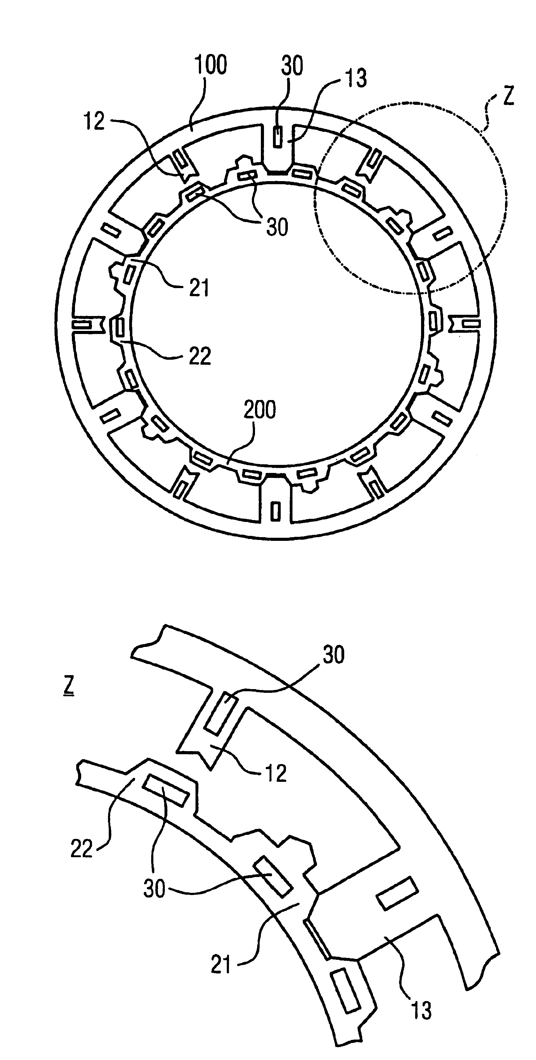
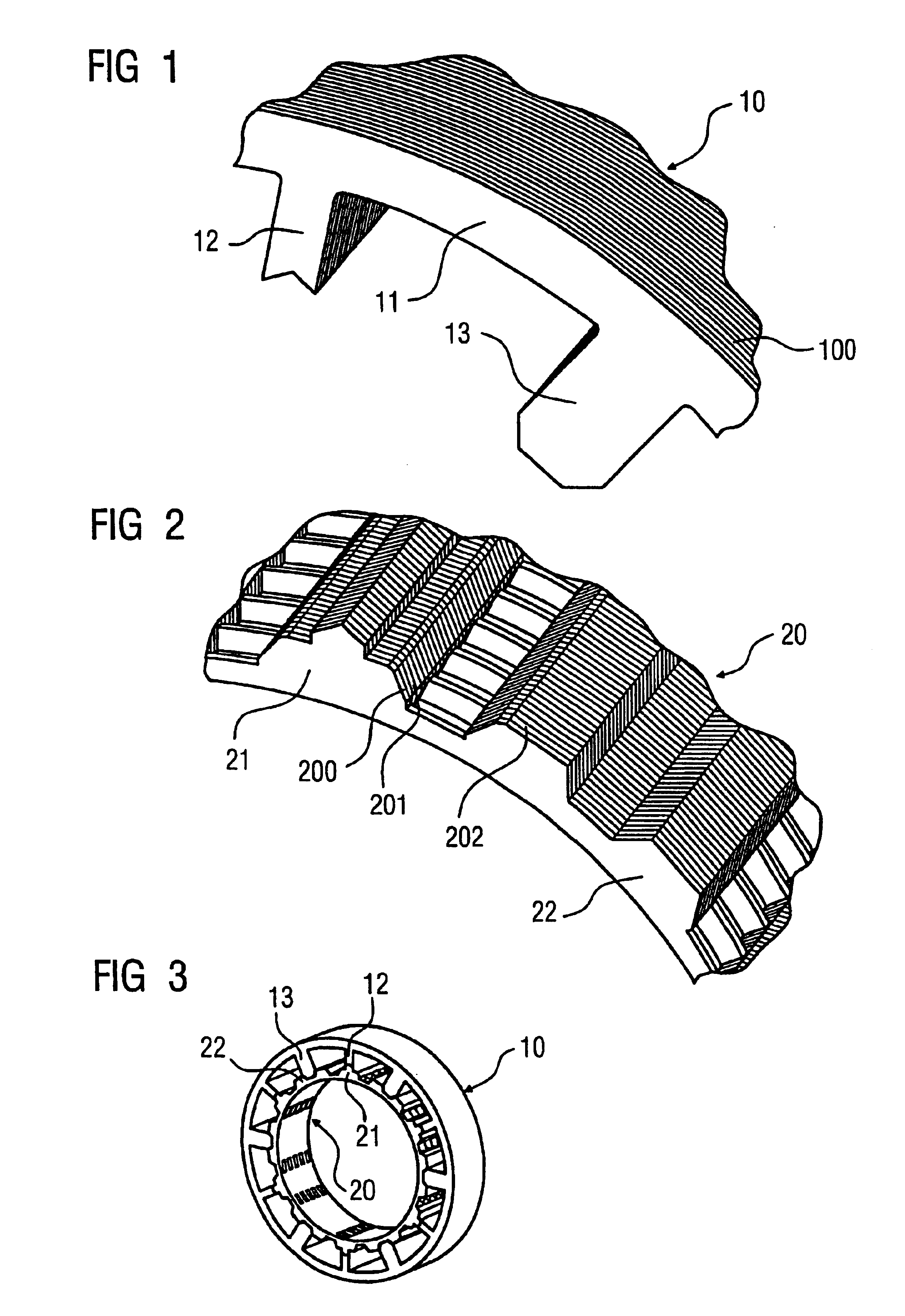
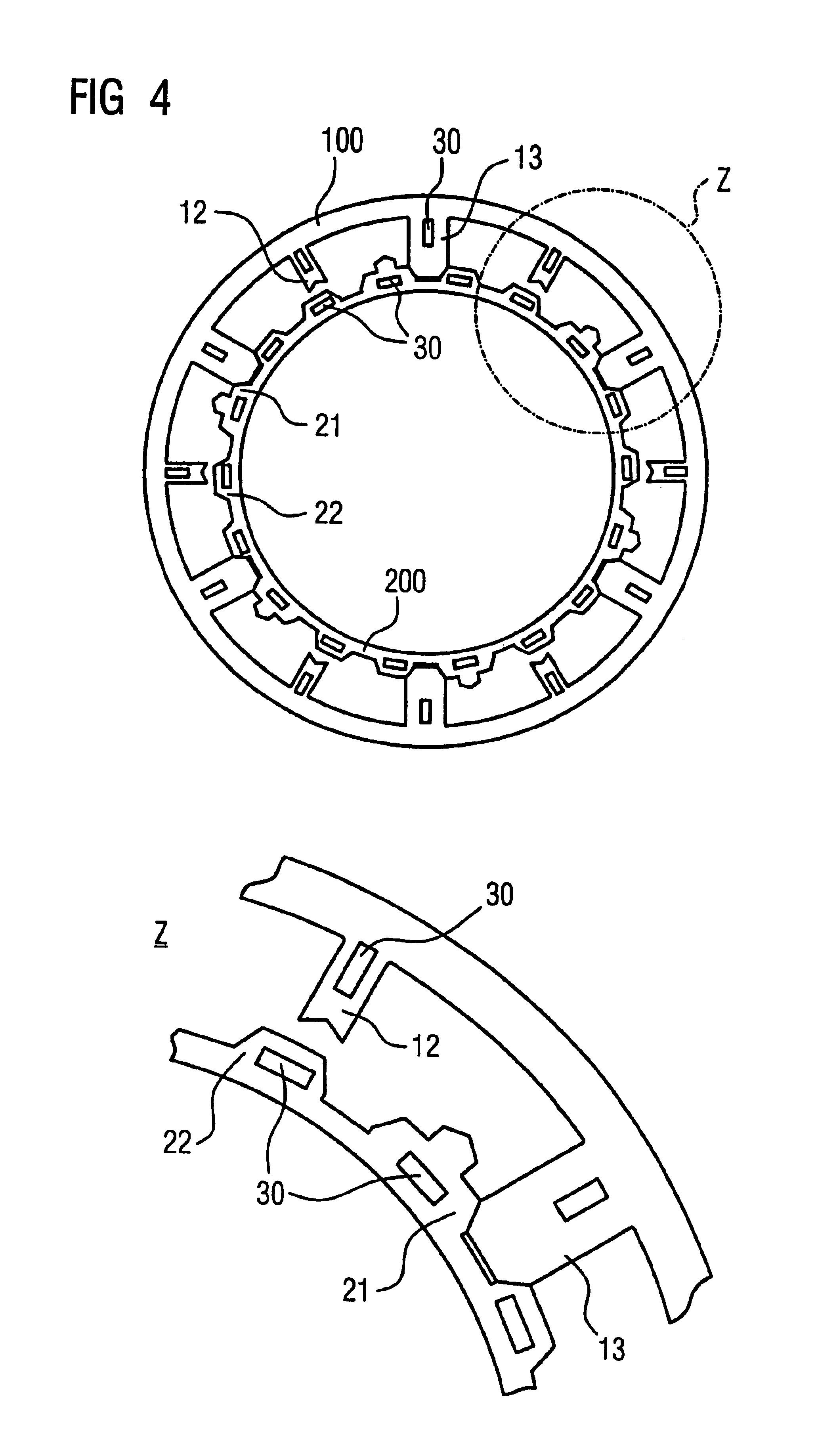
Turning now to the drawing, and in particular to FIG. 1, there is shown a section of a laminated yoke armature for a stator of a harmonic motor. The laminated yoke armature 10 includes a plurality of consecutively arranged individual plates 100 which each have a yoke section 11 and inwardly extending narrow pole teeth 12 and wide pole teeth 13 alternatingly distributed along the circumference. The free ends of the narrow pole teeth 12 have a dovetail shape. The free ends of the wide pole teeth, on the other hand, have beveled edges.

FIG. 2 shows a laminated star armature 20 that fittingly engages with the laminated yoke armature 10. The laminated star armature 20 can also be referred to as a tooth head sleeve or interior stator armature. A narrow tooth head 21 whic...


PUM


Abstract

Stators for harmonic motors are disclosed. The stators are easy to assemble and include a laminated armature made of sheet metal plates. The laminated armature is formed of a substantially cylindrical laminated star armature with a plurality of radially outwardly oriented pole heads distributed along the circumference of the laminated star armature, and a substantially cylindrical laminated yoke armature having radially inwardly oriented pole teeth and arranged radially outside of and concentrically with the laminated star armature. Each of the pole heads is arranged radially adjacent to a corresponding one of the pole teeth. Windings are applied to the pole teeth before the tooth head sleeve or the laminated star armature are inserted in and joined with th laminated yoke armature.

Description

CROSS-REFERENCES TO RELATED APPLICATIONSThis application claims the priority of German Patent Application, Serial No. 102 36 942.9, filed Aug. 12, 2002, pursuant to 35 U.S.C. 119(a)-(d), the disclosure of which is incorporated herein by reference.BACKGROUND OF THE INVENTIONThe invention is directed to laminated armatures made of sheet metal plates for an electric machine, in particular to armatures for the stator of a synchronous machine, as well as to a method for producing a winding arrangement for an electric machine with such armatures.Motors where the number of rotor poles corresponds to an integer multiple, e.g., 2, 4, 5 or 7 of the primary number of stator poles, are referred to as harmonic motors. Stators of so-called harmonic motors have to satisfy specific requirements. The stator teeth of such harmonic motors should advantageously have high and wide tooth heads, and the stator slots should have a high copper fill factor.Laminated stator armatures with slots arranged betwe...

Claims


Application Information

Patent Timeline
Patent Type & Authority Patents(United States)
IPC IPC(8): H02K1/14
CPCH02K1/148
Inventor MULLER, JORGVOLLMER, ROLF
Owner SIEMENS AG
Learn More