Substitution call control system in ATM communication network

a call control system and call control technology, applied in the field of substitution call control system, can solve the problems of high development cost, high cost of each apparatus, and high cost of each apparatus, and achieve the effect of low cost and low cos

Inactive Publication Date: 2005-02-22
JUMIPER NETWORKS INC
View PDF16 Cites 22 Cited by
  • Summary
  • Abstract
  • Description
  • Claims
  • Application Information

AI Technical Summary

Benefits of technology

An object of the present invention is to provide a substitution call control system in which a network terminator and a subscriber terminal are provided with low costs, so that an ATM subscriber network can be constructed in a low cost.

Problems solved by technology

However, there are the following problems in the conventional call control function described above.
The first problem is in that the network terminators 40a to 40c, and the subscriber terminal 50a to 50c are expensive in price.
Because the call control functions are different depending upon the units, the development cost increases.
Also, because the memory capacity is needed for the call control function, each apparatus becomes expensive.
In the second problem, the maintenance when the specification of the call control function is updated takes time and effort.

Method used


Image

  • Substitution call control system in ATM communication network
  • Substitution call control system in ATM communication network
  • Substitution call control system in ATM communication network

Examples


first embodiment

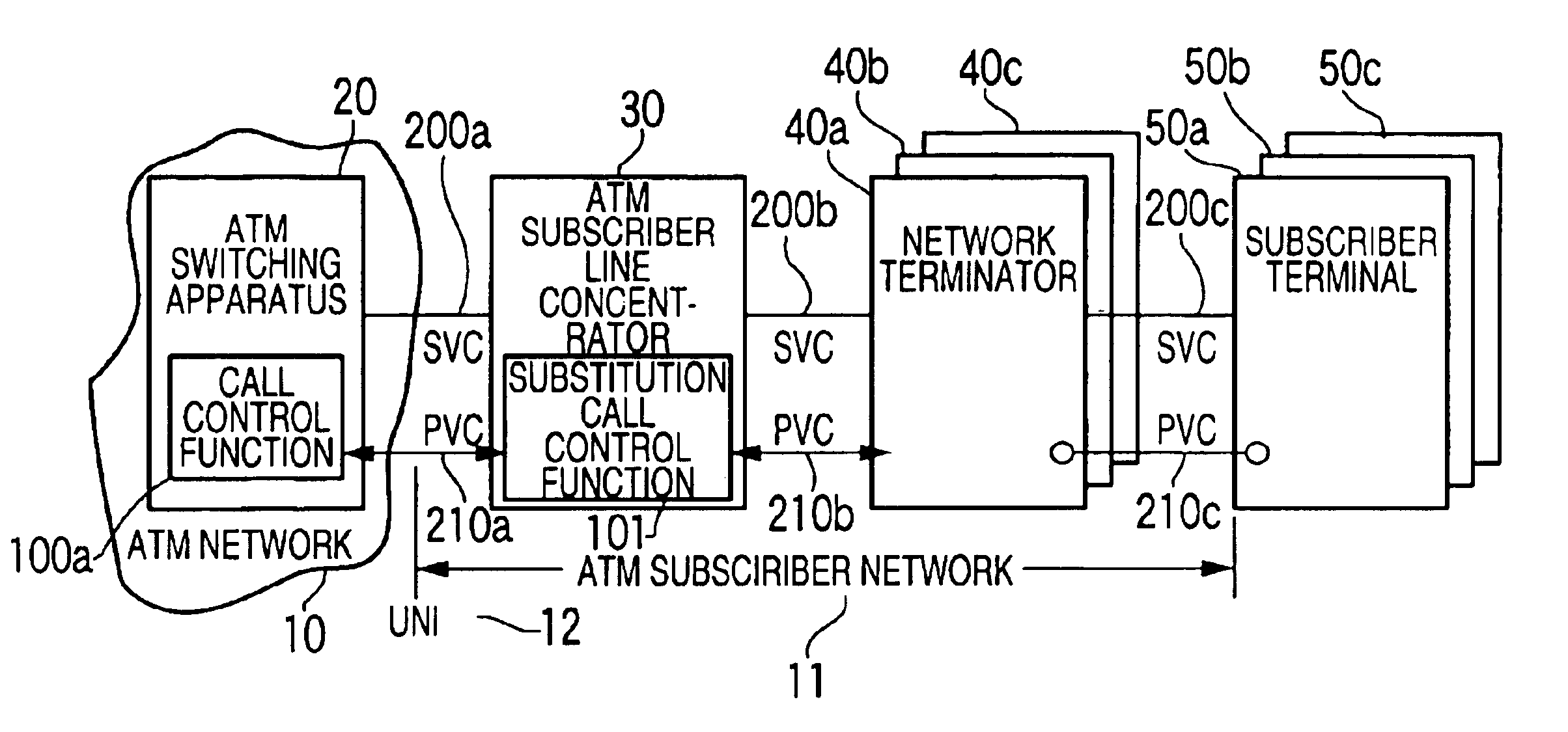
FIG. 5 is a diagram illustrating protocols in the present invention when there is mapped to a TCP / UDP layer, a substitution call control message which is transmitted or received between the substitution call control function 101 and the network terminators 40a to 40c or the subscriber terminal 50a to 50c. The address for the network terminator 40 is registered as the ATM address 302 of the management table 300.

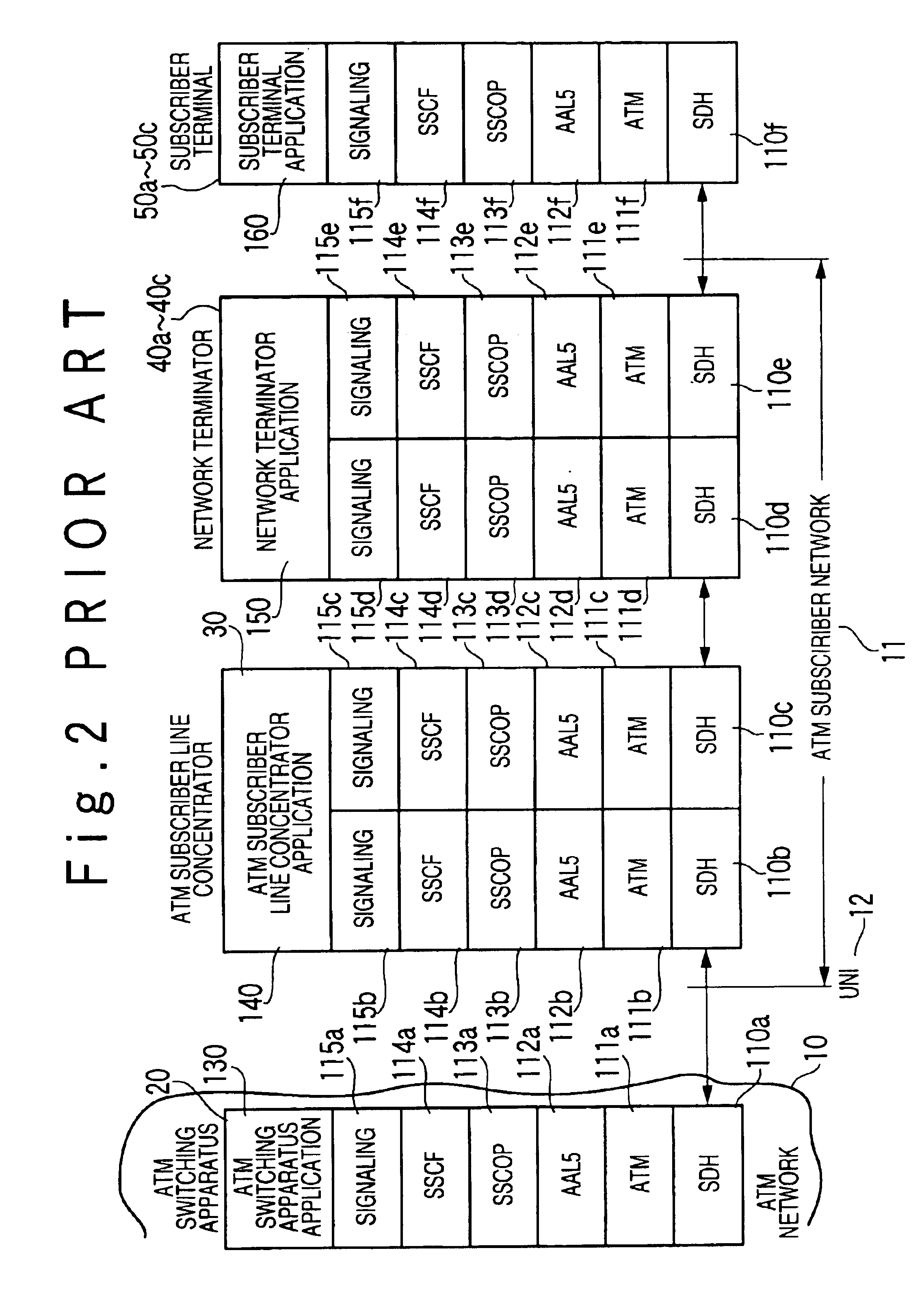
In the UNI 12 between the ATM switching apparatus 20 of the ATM network 10 and the ATM subscriber line concentrator 30 of the ATM subscriber network 11,SDH (Synchronous Digital Hierarchy) layers 110a and 110b, ATM layers 111a and 111b subject to ITU-T recommendation I.361,AAL5 layers 112a and 112b subject to ITU-T recommendation I.363,SSCOP (Service Specific Connection Oriented Protocol) layers 113a and 113b subject to ITU-T recommendation Q. 2110,SSCF (Service Specific Coordination Function) layers 114a and 114b subject to ITU-T recommendation Q. 2130, andsignaling layers 115...

second embodiment

FIG. 6 is a diagram is illustrating the protocol in the present invention when the substitution call control message transmitted and received between the substitution call control function 101 and the network terminators 40a to 40c or the subscriber terminal 50a to 50c is mapped to an ATM cell.

The UNI 12 between the ATM switching apparatus 20 and the ATM subscriber line concentrator 50 includes:SDH layers 11a and 110b, ATM layers 111a and 111b, AAL5 layers 112a and 112b, SSCOP layers 113a and 113b, SSCF layers 114a and 114b, andsignaling layers 115a and 115b as the call control protocol, like the case of FIG. 5. The UNI 12 is controlled by ATM switching apparatus application 130 and the ATM subscriber line concentrator application 140 with the substitution call control function 101.

The ATM subscriber line concentrator application 140 which is provided with the substitution call control function 101, and the network terminators application 150. The substitution call control protocol ...


PUM


Abstract

A substitution call control system includes an ATM (Asynchronous Transfer Mode) subscriber network of an ATM communication network. The ATM subscriber network includes a plurality of network terminators respectively connected with a plurality of subscriber terminals, and an ATM subscriber line concentrator, which accommodates VCs (Virtual Connection) to the plurality of network terminators, and is connected with a ATM switching apparatus of the ATM network through a UNI (User-Network Interface). The ATM subscriber line concentrator includes a substitution call control function to substitute for the plurality of network terminators and the subscriber terminals for a call control.

Description

BACKGROUND OF THE INVENTION1. Field of the InventionThe present invention relates to a call control in an ATM (Asynchronous Transfer Mode) subscriber communication network. More particularly, the present invention relates to a substitution call control system which substitutes a call control from a subscriber terminal in an ATM line concentrator.2. Description of the Related ArtThere are PVC (Permanent Virtual Channel) and SVC (Switched Virtual Channel) in an ATM communication network, and the establishment and release of a SVC connection is controlled.As protocol for the control of establishment and release of the SVC connection, the following protocols are used. That is, they are:ITU-T recommendation Q.2110 (to be referred to as SSCOP hereinafter),ITU-T recommendation Q.2130 (to be referred to as SSCF hereinafter),ITU-T recommendation Q.2931 and ITU-T recommendation Q.2971,ATM Forum Technical Committee ATM UNI (User-Network Interface) Specification Version 3.1 (to be referred to a...

Claims


Application Information

Patent Timeline
Patent Type & Authority Patents(United States)
IPC IPC(8): H04Q11/04H04L12/56H04L47/43H04Q3/00
CPCH04Q11/0478H04L2012/5603H04L2012/5614H04L2012/5658H04L2012/563
Inventor TANAKA, MASASHI
Owner JUMIPER NETWORKS INC
Why Eureka
Try Eureka