Electromagnetic counter with built-in illumination device

a technology of electromagnetic counter and illumination device, which is applied in the field of electromagnetic counter, can solve the problems of increasing maintenance work and cost, difficulty in reading a number displayed on the counter, and difficulty in installing an illumination lamp inside the equipment or the electromagnetic counter, and achieves the effects of reducing maintenance and cos

Active Publication Date: 2005-02-22
CONTEX +1
View PDF4 Cites 15 Cited by
  • Summary
  • Abstract
  • Description
  • Claims
  • Application Information

AI Technical Summary

Benefits of technology

In the present invention, the configurations described above are employed, thereby obtaining the following effects. In the first aspect of the present invention, the light emitting diode mounted on the flexible board is built in as the illumination means of the counter display section. Accordingly, it is easy to install the illumination means even in the confined space within the compact electromagnetic counter. Further, the light emitting diode does not use a filament, resulting in minimum maintenance as compared with a miniature light bulb. When the electromagnetic counter is installed in equipment, the circuit wiring or a lead wire of the equipment is simply connected to the end terminal section of the printed wiring formed on the flexible board to complete the installation, so that the electromagnetic counter with built-in illumination means is extremely useful for installing in a compact game machine, a copier, a printer and the like.
In the second aspect of the present invention, the cover member covers the frame member provided with the counter constituent elements such as the electromagnet, anchor and number wheels. Accordingly, the electromagnetic counter has superior dust resistance, and is easy to assemble and reduce in size. The confined space between the frame member and cover member is effectively utilized. Accordingly, the electromagnetic counter with built-in illumination means has superior reliability in the counting operation, and can be manufactured at low cost, thereby obtaining high product value.
In the third aspect of the present invention, the flexible board with the light emitting diode is attached to the frame member. Accordingly, it is easy to install the illumination means. Further, the notch is formed in the surface of the frame member, so that the light emitting diode can be attached at a thick wall portion of the frame member. Accordingly, it is not necessary to provide an additional space for the illumination means, thereby obtaining the effects described above.
In the fourth aspect of the present invention, when the electromagnetic counter is installed in the equipment, the installation is completed with a simple process of soldering the circuit wiring of the equipment to the end terminal section at the end of the flexible board protruding outside, and inserting the connection terminal of the electromagnet into the wiring board. Accordingly, in addition to the effects described above, the electromagnetic counter is extremely useful for various types of equipment such as a compact game machine, a copier and a printer.
In the fifth aspect of the present invention, the end section of the lead wire connected to the printed wiring of the flexible board engages the groove formed in the frame member. Accordingly, in addition to the effects described above, even when a force is applied in a direction of pulling out the lead wire, the force is applied directly to the soldered section of the lead wire and the printed wiring, thereby preventing the lead wire from being pulled out and improving the reliability of the illumination means in which the lead wire is connected.
In the sixth aspect of the present invention, the multicolor light emitting diode is used, so that it is possible to arbitrarily select a color of the emitted light. Accordingly, in addition to the effects described above, when a plurality of electromagnetic counters is installed to accommodate a plurality of count elements, it is possible to change the color of the emitted light for each electromagnetic counter, thereby reducing reading error of the count elements.

Problems solved by technology

Since the inside of the equipment is dark and the counter is not provided with a light emitting function, it is difficult to read a number displayed on the counter.
Accordingly, it is extremely difficult to install an illumination lamp inside the equipment or the electromagnetic counter.
Further, even if it is arranged to provide a confined space for installing a miniature light bulb, it is necessary to periodically replace the light bulb due to the limited service life of the filament of the light bulb, thereby increasing maintenance work and cost due to the confined space.
In a case of an electromagnetic counter in which an electromagnet, anchor and number wheels are disposed in a housing and a cover member is fixed to a frame member, it is essentially impossible to replace a light bulb, so that the entire electromagnetic counter needs to be replaced.

Method used


Image

  • Electromagnetic counter with built-in illumination device
  • Electromagnetic counter with built-in illumination device
  • Electromagnetic counter with built-in illumination device

Examples


Embodiment Construction

Hereunder, embodiments of the present invention will be explained with reference to the accompanying drawings. An electromagnetic counter of the present invention is not limited to the embodiments.

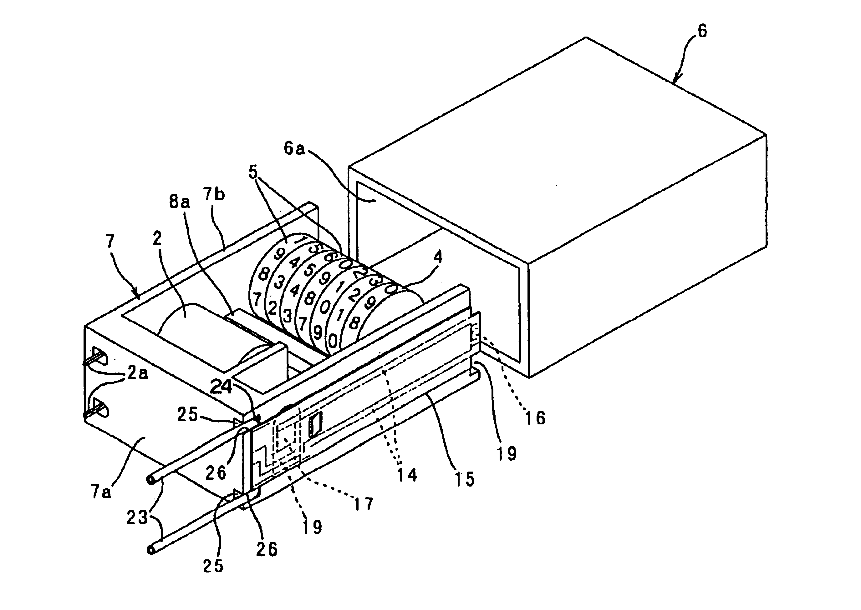
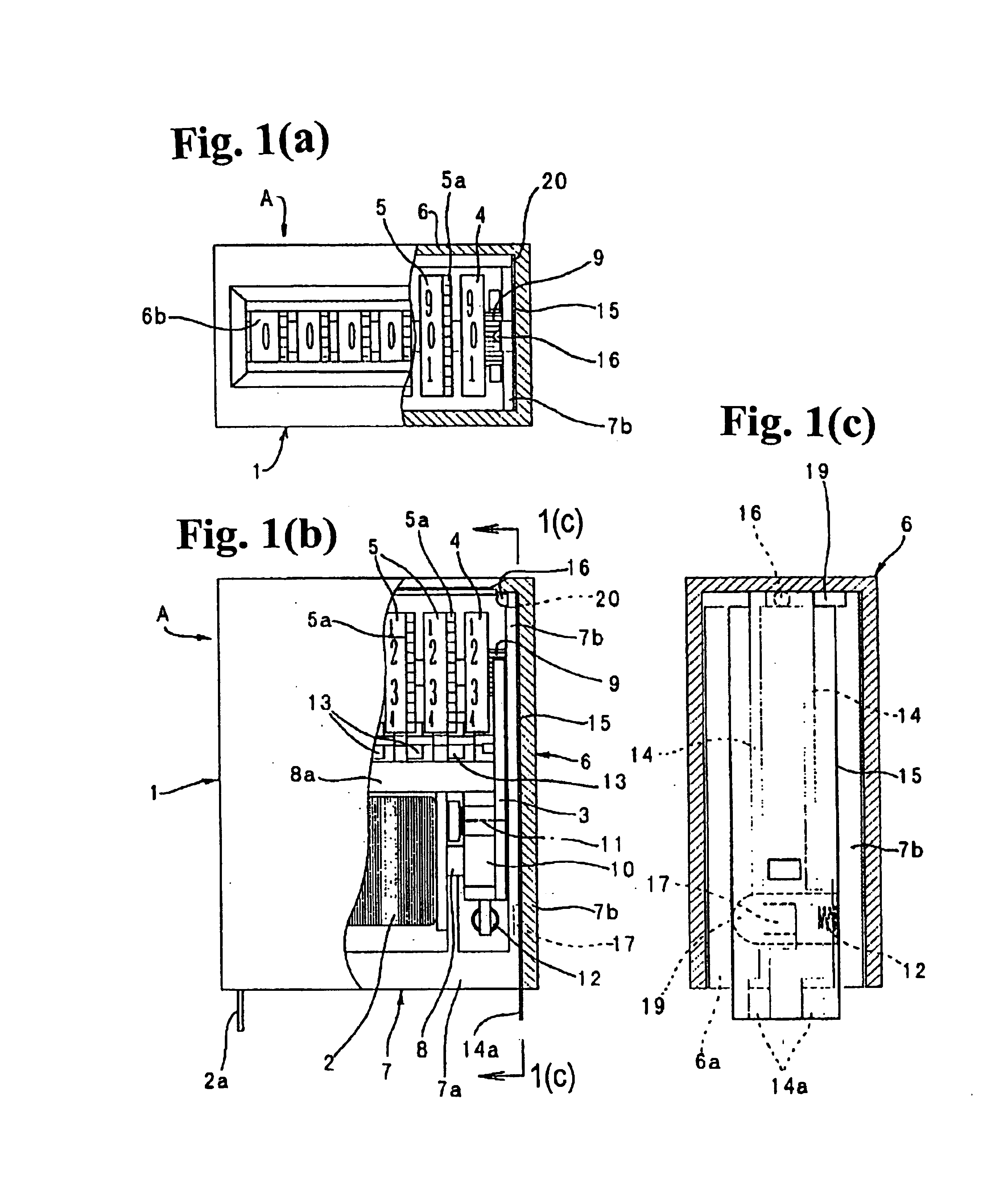
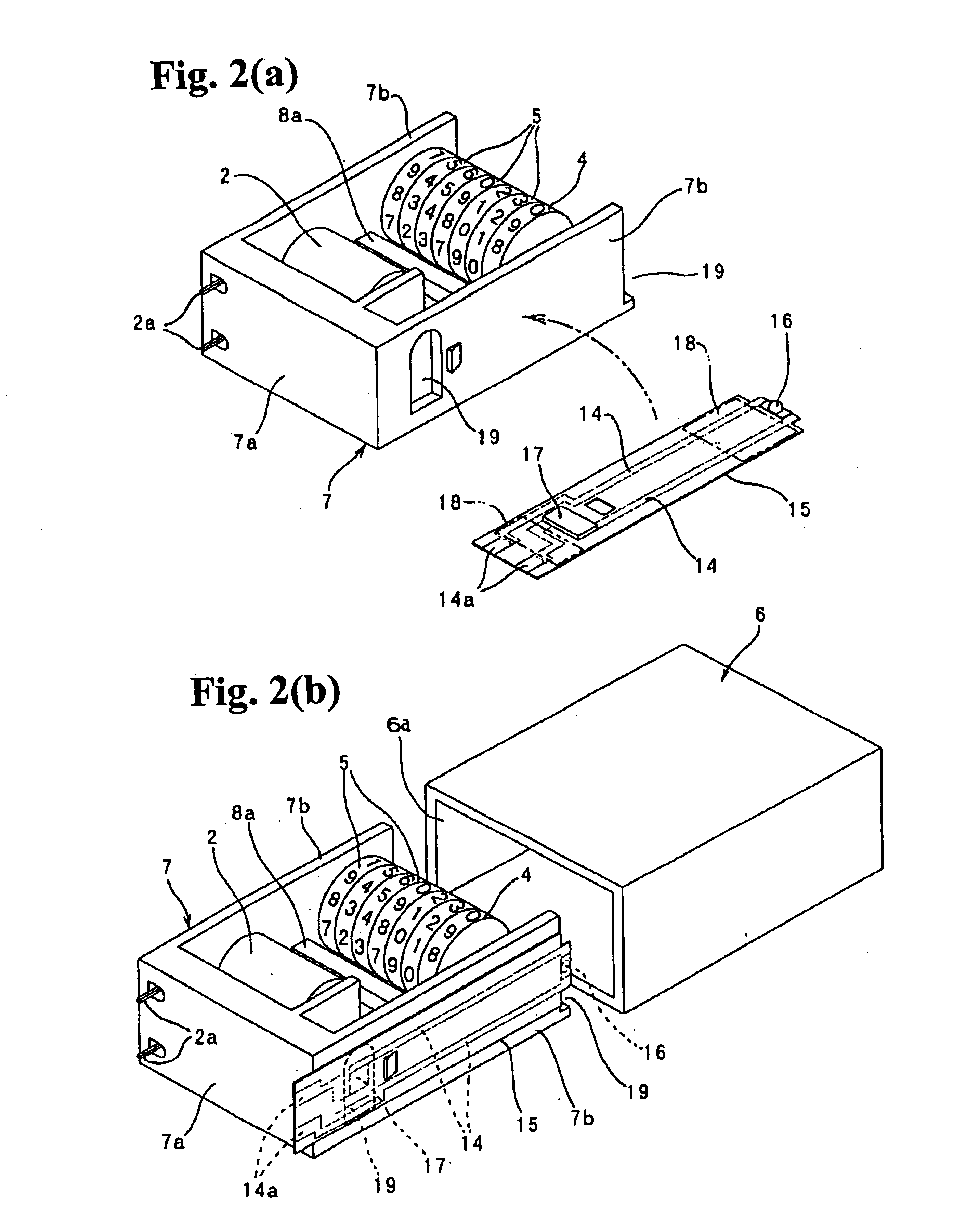
As shown in FIGS. 1(a)-1(c) and 2(a), 2(b), an electromagnetic counter A is provided with an electromagnet 2, an anchor 3, a lowest digit number wheel 4, upper digit number wheels 5 and an illumination means inside a case 1. The illumination means illuminates the number wheels 4 and 5, so that displayed numbers can be easily read even in a dark location.

The case 1 is composed of a roughly box-shaped cover member 6 and a frame member 7 with a periphery thereof covered by the cover member 6. The cover member 6 is provided with an opening 6a as an insertion hole for the frame member 7 on an arbitrary side (e.g., backside) and a window 6b as a counter display section on another arbitrary side (e.g., front side). The frame member 7 has a roughly U-shape in which a base section 7a closes the ope...


PUM


Abstract

An electromagnetic counter includes a case, an electromagnet, an anchor rotatable through magnetization and demagnetization of the electromagnet, and number wheels rotated by a predetermined angle according to the rotation of the anchor. A flexible board with a light emitting diode is disposed in a confined space in the case for illuminating the number wheels.

Description

BACKGROUND OF THE INVENTION AND RELATED ART STATEMENTThe present invention relates to an electromagnetic counter and, more particularly, relates to an improvement of an illumination mechanism of an electromagnetic counter installed in a device.Conventionally, as disclosed in, for example, patent reference 1, there has been known an electromagnetic counter provided with at least an electromagnet, an anchor rotatable through magnetization and demagnetization of the electromagnet, and a lowest digit number wheel having a ratchet gear on a side thereof for engaging a tab formed at an end of the anchor. The electromagnetic counter also includes a predetermined number of upper digit number wheels having transmission gears on sides thereof, and pinions disposed between the number wheels for increasing figures.In the electromagnetic counter, the electromagnet, anchor and number wheels are disposed inside a case to keep an iron core magnetized by the electromagnet away from iron paticles so ...

Claims


Application Information

Patent Timeline
Patent Type & Authority Patents(United States)
IPC IPC(8): G06M1/10G06M1/22G06M1/02G06M1/00
CPCG06M1/22
Inventor ISHIDA, NORIYUKI
Owner CONTEX
Why Eureka
Try Eureka