Redundant precision time keeping for utility meters

a technology of utility meters and precision time keeping, applied in the field of utility meters, can solve the problems of degrading demand meter data, affecting the accuracy of meter data, and imposing significant labor costs on manual meter readings, and achieves the effect of smooth transition and accurate picture of certain behaviors

Inactive Publication Date: 2005-02-22
LANDIS GYR LLC
View PDF35 Cites 83 Cited by
  • Summary
  • Abstract
  • Description
  • Claims
  • Application Information

AI Technical Summary

Benefits of technology

The present invention fulfills the above need, as well as others, by employing a clock circuit that generates clock signals based on a precision time signal and timing information derived from power line signals. Because both systems are employed, highly accurate clock information is available in the meter in the event that either of the sources of timing information becomes unavailable.
A first embodiment of the present invention includes an apparatus for generating precision clock information, comprising a source of power line timing information, a source of externally-generated precision time information, and a timing circuit. The timing circuit is coupled to the source of externally-generated precision time information to receive a precision time information therefrom, and is operable to generate clock information based on the precision time signal. The timing circuit is further operable to generate clock information based on the power line timing information.
Preferably, the power line timing information is synchronized to the precision time signal within the meter to ensure a smooth transition from relying on the precision time signal to relaying on the power line timing information.
Another embodiment of the present invention is a meter that obtains energy consumption data and stores energy consumption data in a memory associated with a time record. The meter includes a source of power line timing information, a source of externally-generated precision time information, and a timing circuit. The timing circuit is coupled to the source of externally-generated precision time information to receive a precision time signal therefrom, and is operable to generate clock information based on the precision time signal. The timing circuit is further operable to generate clock information based on the power line timing information. The time record is based on the clock information.
Accordingly, the above described meter thus stores energy consumption data associated with a time record, wherein the time record is generated using redundant sources of timing information that are generated external to the meter and therefore are standardized. Such data may then be compared to other stored energy consumption data and time records of similar meters to obtain an accurate picture of certain behaviors of an electrical system. Without standardized clocking, minor variances in time-keeping can render comparative data from different meters largely meaningless.
The above described features and advantages, as well as others, will become more readily apparent to those of ordinary skill in the art by reference to the following detailed description and accompanying drawings.

Problems solved by technology

Such manual meter reading imposes significant labor costs and is vulnerable to transportation problems and human error.
An inaccurate clock can substantially degrade demand meter data, thereby resulting in significant overcharging or undercharging.
One difficulty of performing analysis on the captured waveforms of several meters is temporally aligning the captured waveforms.
However, commonly used electronic clocks in electronic meters are not highly synchronized to each other, or in fact, to any external equipment.
While such a practice increases the accuracy of the meter clock circuits, the 60 Hz signal is not always dependable, and indeed may become unavailable during a power sag or power outage.
Such a drawback is particularly problematic because power quality meters require accurate timing precisely for those times when the power line signal becomes unavailable.
The drawback of relying on a GPS signal is that the GPS signal is not always available in real conditions.

Method used


Image

  • Redundant precision time keeping for utility meters
  • Redundant precision time keeping for utility meters
  • Redundant precision time keeping for utility meters

Examples


Embodiment Construction

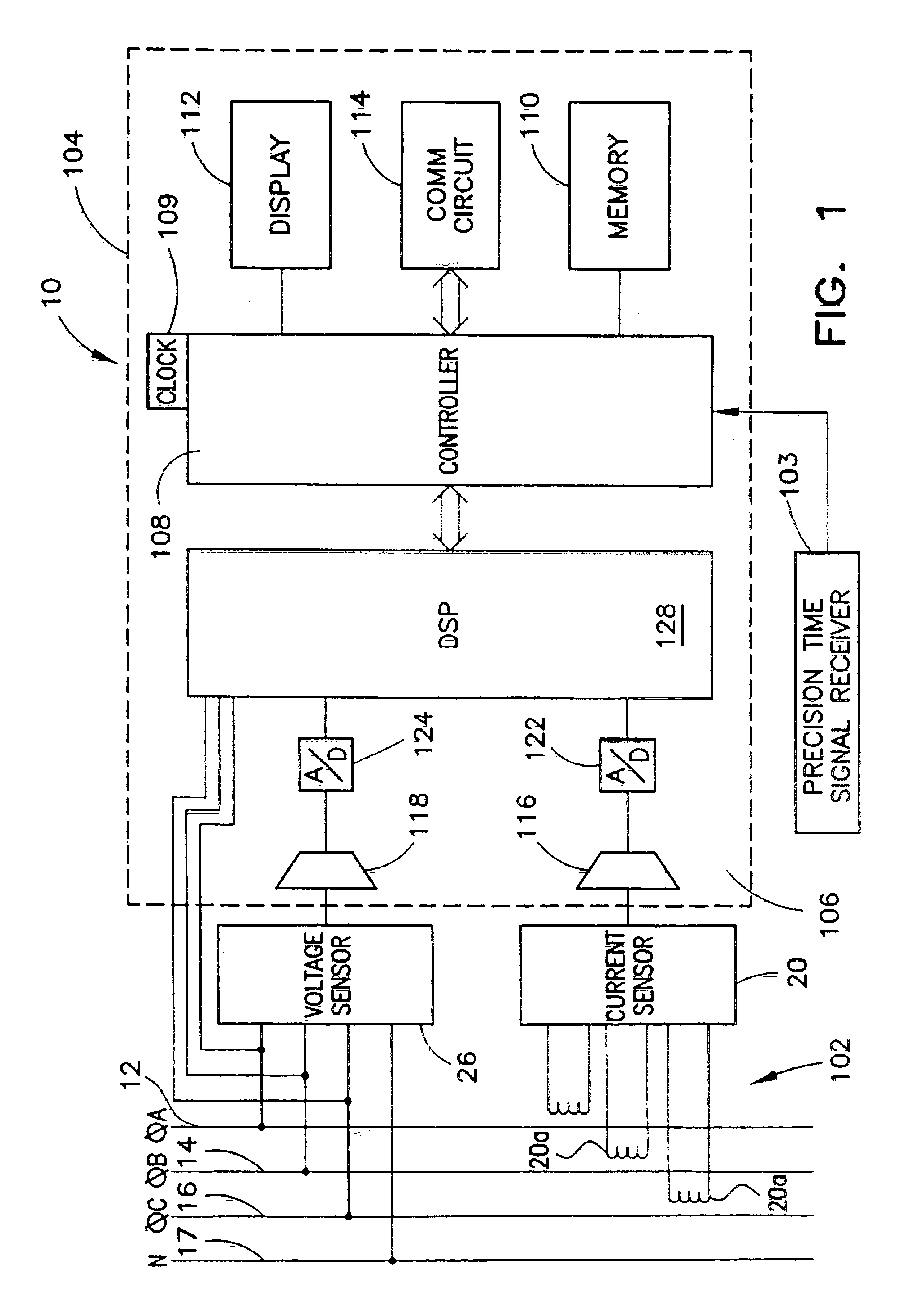
FIG. 1 shows a block diagram of an exemplary electricity meter 10 according to the present invention. The meter 10 is shown in FIG. 1 configured to measure power consumed over a three phase power system that includes power line A 12, power line B 14, and power line C 16. The three phase power system further includes a neutral line N 17. The three phase power system delivers power from a source, not shown, to a load not shown, through the power lines 12, 14, 16 and 17. It will be appreciated, however, that the present invention may be readily adapted to other types of electrical systems.

The electricity meter 10 essentially comprises sensor circuitry 102 and a measurement circuit 104. The sensor circuitry 102 includes a polyphase current sensor 20 and a polyphase voltage sensor 26. The measurement circuit 104 further comprises a conversion circuit 106, a controller 108, a memory 110, a display 112, and a communication circuit 114.

The current sensor 20 is connected to receive a signal ...


PUM


Abstract

An apparatus for generating precision time signals includes a source of power line timing information, a source of precision time signals, and a timing circuit. The timing circuit is coupled to the source of precision time signals to receive a precision time signal there from, and is operable to generate clock information based on the precision time signal. The timing circuit is further operable to generate clock information based on the power line timing information.

Description

FIELD OF THE INVENTIONThe present invention relates generally to utility meters, and more particularly, to utility meters that maintain a real-time clock.BACKGROUND OF THE INVENTIONUtility meters are devices that, among other things, measure the consumption of a utility provided commodity, such as electric energy, gas, or water, by a residence, factory, commercial establishment or other such facility. Utility service providers employ utility meters to track individual customers' usage of utility provided commodities. Utilities track customer usage for many purposes, including billing and tracking demand for the relevant consumed commodity.Increasingly, utility service providers prefer utility meters that employ electronic circuitry to perform measurement and communications operations. Electronic circuitry reduces the number of moving parts required to perform measurement operations, resulting in increased accuracy as well as higher reliability. Further, a utility meter is typically ...

Claims


Application Information

Patent Timeline
Patent Type & Authority Patents(United States)
IPC IPC(8): G01R22/00
CPCG01R22/00
Inventor RANDALL, BRUCE EVERETTJENRETTE, WILLIAM IAN
Owner LANDIS GYR LLC
Why Eureka
Try Eureka