

Processor-controlled carving and multi-purpose shaping device
a technology of multi-purpose shaping and processing device, which is applied in the direction of carving, flat surface machines, wood charring/burning, etc., can solve the problems of limited detail and achieve the effect of convenient operation
- Summary
- Abstract
- Description
- Claims
- Application Information
AI Technical Summary
Benefits of technology
Problems solved by technology
Method used
Image

Examples
Embodiment Construction
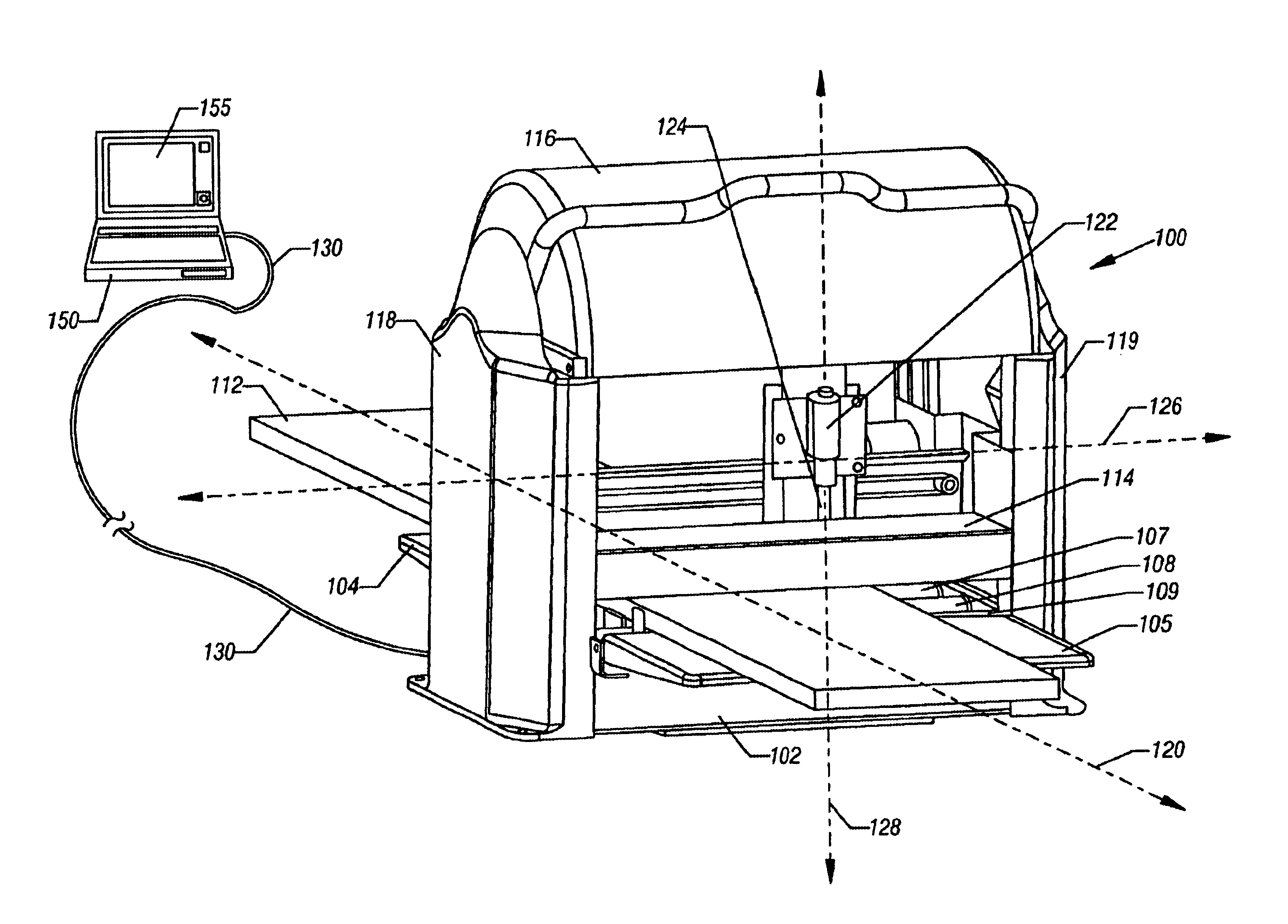
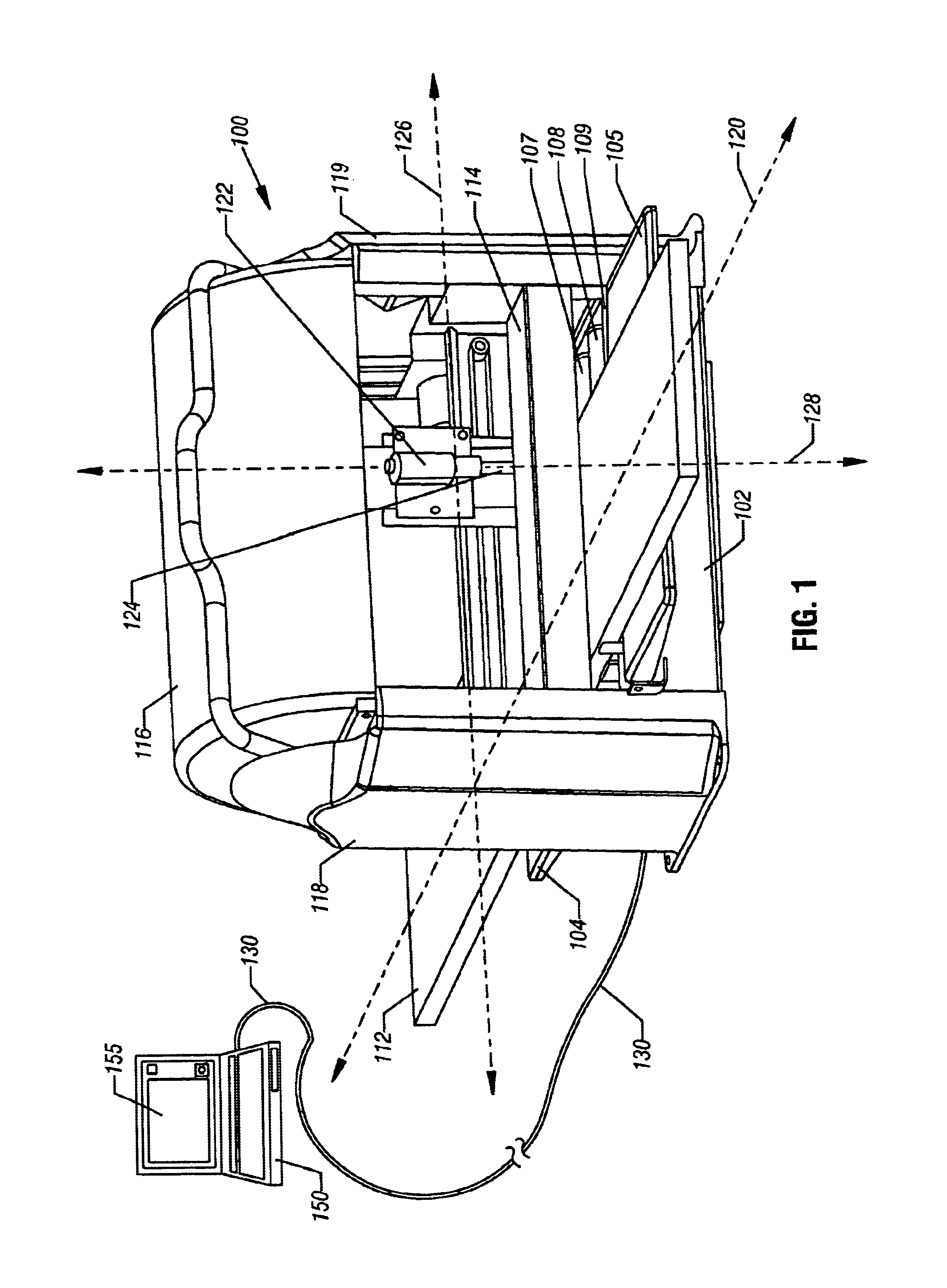
One embodiment of the present invention is a compact, low-cost, lightweight, versatile and easy-to-operate processor-controlled carving and multi-purpose shaping device (“PCCMPS”) that can be employed to produce three-dimensional carvings and to otherwise shape surfaces of a work piece composed of one or a combination of rigid or semi-rigid materials, such as wood, plastic, laminates or other such materials. FIG. 1 shows a perspective view of a PCCMPS machine that represents one embodiment of the present invention. This embodiment will be described in detail below. Note that numerical labels are reused in subsequent figures to label the component or feature that they first identify, in the interest of clarity and brevity.
As shown in FIG. 1, the PCCMPS machine 100 includes a base 102, feed trays 104 and 105, and lower rollers 107-109 (one lower roller obscured in FIG. 1) that together comprise a horizontal surface, or truncated bed, that supports and horizontally translates a work pi...
PUM
| Property | Measurement | Unit |
|---|---|---|
| speed | aaaaa | aaaaa |
| size | aaaaa | aaaaa |
| physical size | aaaaa | aaaaa |
Abstract
Description
Claims
Application Information