Flexible pouch fitment structure

a flexible and pouch technology, applied in the field of pouches, can solve the problems of inability to obtain consistent packages, wear of sealing jaws, and inability to achieve uniform packaging, and achieve the effect of high speed

Inactive Publication Date: 2005-03-01
ILLINOIS TOOL WORKS INC
View PDF11 Cites 69 Cited by
  • Summary
  • Abstract
  • Description
  • Claims
  • Application Information

AI Technical Summary

Benefits of technology

It is a principal object of the present invention to provide an improved fitment with canoe-sh

Problems solved by technology

Unfortunately, in practice, fitments injection molded of polyethylene, polypropylene and the like often vary somewhat dimensionally during manufacture.
Also, in time, the sealing jaws wear and such wear may not be uniform.
As a result, du

Method used


Image

  • Flexible pouch fitment structure
  • Flexible pouch fitment structure
  • Flexible pouch fitment structure

Examples


Embodiment Construction

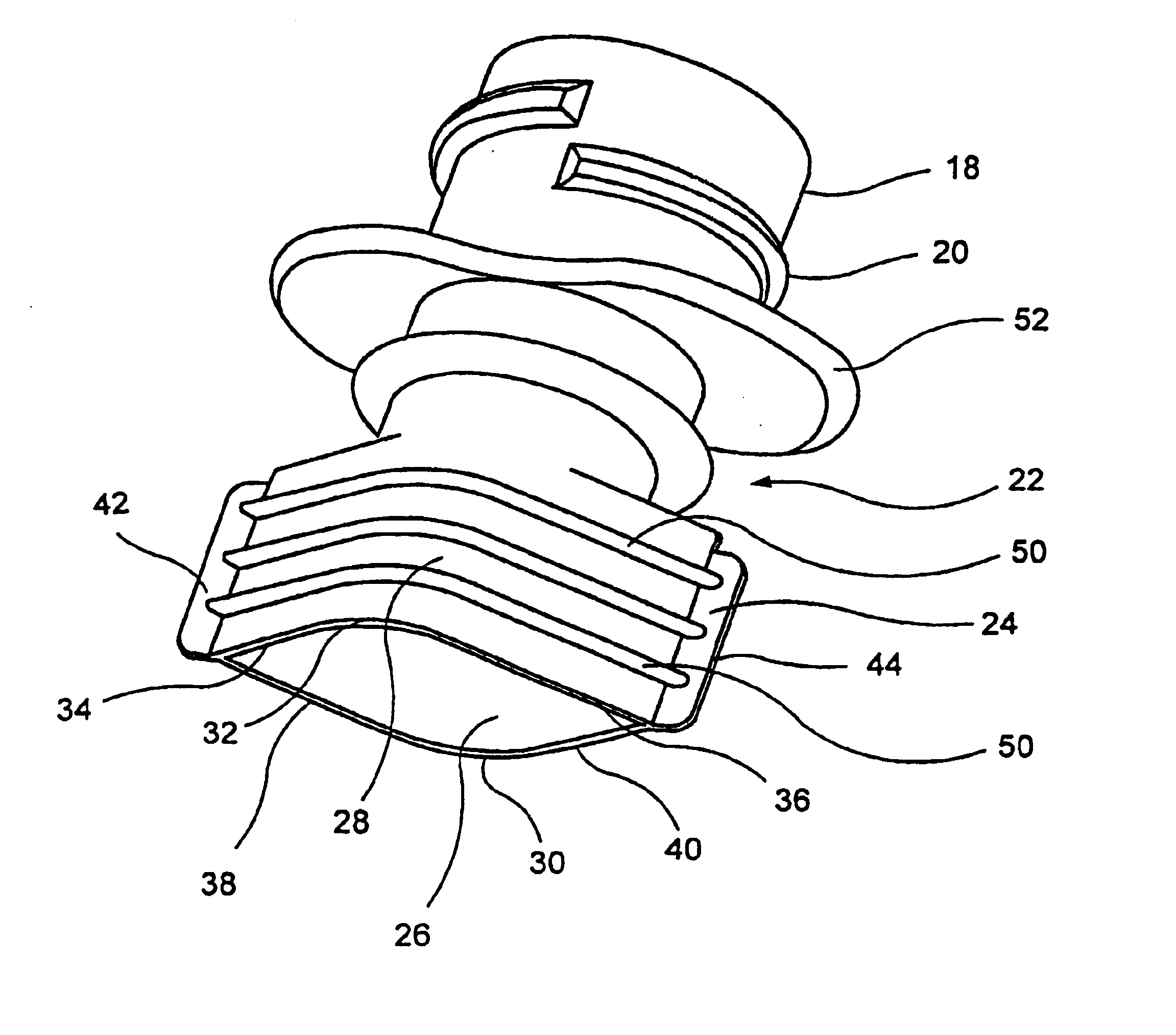
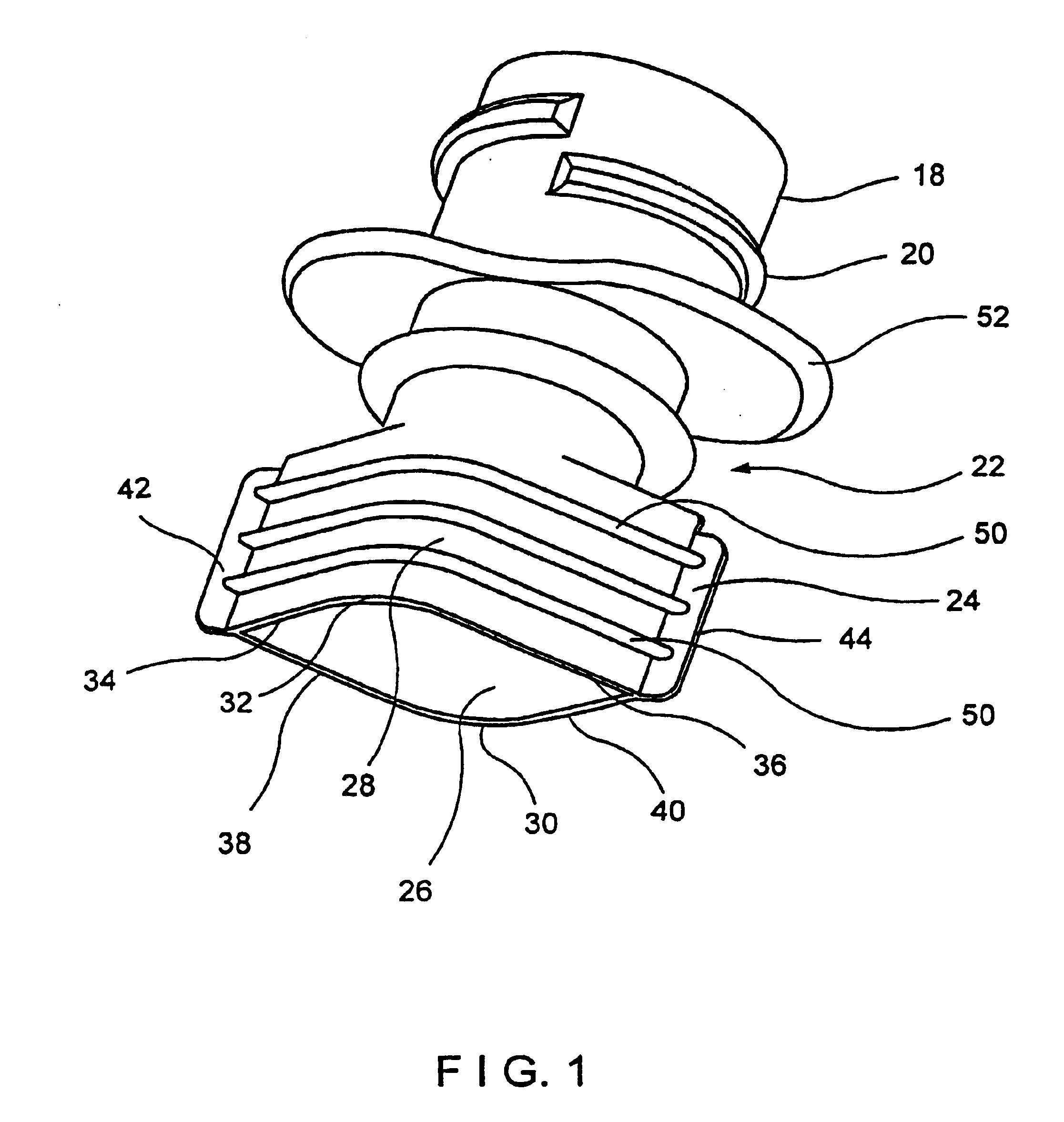
Reference is now made to the drawings and to FIG. 4 in particular wherein a package 10 is depicted. The package is formed of two sheets of a suitable film for the contents to be held. In this regard, the film may be a laminate, the layers of which have desired barrier or other properties for the product to be contained and an appropriate sealant layer for bonding to each other and to the fitment. The sheets are sealed to each other in a zone 12 extending about the package periphery, thereby forming a leak proof inner area 14 into which the package contents are captured. A spout 16 extends from the package top to the inner area 14. The spout 16 conveniently includes a center cylindrical neck 18 which carries external threads 20 for an associated cap. The spout 16 is formed using a fitment 22 as shown in FIG. 1. Fitment 22 is conveniently injection molded of a thermoplastic material such as polyethylene or polypropylene and the canoe section is relatively thin, on the order of 26-28 m...


PUM

PropertyMeasurementUnit
Flexibilityaaaaaaaaaa

Abstract

A flexible plastic fitment for providing spouts for pouches formed of sheet material. The fitment includes a pair of opposed side walls each having a center portion formed from diametrically opposed segments of a common cylinder and straight segments that blend respectively into the cylindrical segments on opposite sides of the common cylinder. The side walls are joined together at both ends thereof to form a canoe shape. A cover, which provides the only support for the side walls joins the top edges of the canoe shape and extends at both ends of the canoe shape between the cylindrical segments and the joined ends. A thin fin extends from each end of the joined side walls. A method of and apparatus for attaching the fitment by distending the side walls outwardly while urging the sheet material toward the side walls is also disclosed.

Description

BACKGROUND OF THE INVENTIONThe present invention relates to fitments and in particular to a spout fitment for a flexible package.Fitments are often used to provide a pouring spout for containers formed of flexible films. It has heretofore been proposed to use a fitment / spout with a canoe-shaped base that serves to provide a smooth, gradual transition between the plies of film from which the package is to be formed and the pouring spout which is coaxial with the center of the fitment. Common wisdom taught that the fitment canoe section should be relatively rigid so as not to misshape the center spout section when the fitment is subjected to the heat and pressure needed to seal the package film to the fitment. This, in turn, required that the sealing jaws as well as the fitments be precisely sized to assure the formation of tight seals. Frequently it is necessary to attach the fitment with one set of sealing jaws and then seal the pouch film with a second different set of jaws. Unfort...

Claims


Application Information

Patent Timeline
IPC IPC(8): B31B19/84B31B19/00B65D75/52B65D75/58B31B1/84B65D33/38
CPCB29C65/18B29C66/30223B29C66/53263B31B19/84B65D75/5883B29C66/63B65D2575/583B31B2219/9054B29L2031/7128B29C66/232B31B70/844B29C66/242B29C66/7234B29C66/1122B65D33/00
Inventor KOBETSKY, ROBERT G.MALIN, ART
Owner ILLINOIS TOOL WORKS INC
Why Eureka
Try Eureka