Method and apparatus for assembly of stair forms

a technology for stair forms and apparatuses, applied in the field of construction forms, can solve the problems of time-consuming and wasteful methods for creating stair forms, concrete work notoriously messy, and the back surface of the apparatus is not well oriented, so as to achieve the effect of time-consuming and wasteful

Inactive Publication Date: 2005-03-01
RELLERGERT LEROY J
View PDF41 Cites 12 Cited by
  • Summary
  • Abstract
  • Description
  • Claims
  • Application Information

AI Technical Summary

Benefits of technology

The present invention relates to construction forms and more specifically to a device for making concrete forms for making stairs. Pouring concrete requires a form to hold the liquid concrete until it can dry to its solid form. The top surface of the wet concrete is left open to allow excess material removal. Creating a form to pour stairs involves securing a set of risers to a set of stringers. The risers contain the wet concrete and when removed correspond to the rise of each step. The top surface of the wet concrete hardens to form the tread of each step. Currently, a stair form is created by cutting portions out of a piece of wood (see FIGS. 8-9). Removing the outline of the stairs, including the thickness of the risers and a finishing space, forms a stringer. The stringer is then hung in place by anchoring at a floor elevation and securing at a landing elevation. Additional stringers are added at regular intervals between the right and left sides of the desired stairs. A portion of each riser is removed to allow a finish tool access to the portion of the tread adjacent the next rise. The risers are then secured at a right angle to the stringer using an additional block of wood attached to both the stringer and the riser. After the concrete dries, the risers and stringers are removed and the stringers must be discarded because of the unlikelihood of needing that exact configuration. This method of creating stair forms is time consuming and wasteful. There is a need for a system that is quicker and allows reuse of the stringers.

Problems solved by technology

This method of creating stair forms is time consuming and wasteful.
Concrete work is notoriously messy and the back surface of the apparatus does not pivot well when dirty.

Method used


Image

  • Method and apparatus for assembly of stair forms
  • Method and apparatus for assembly of stair forms
  • Method and apparatus for assembly of stair forms

Examples


Embodiment Construction

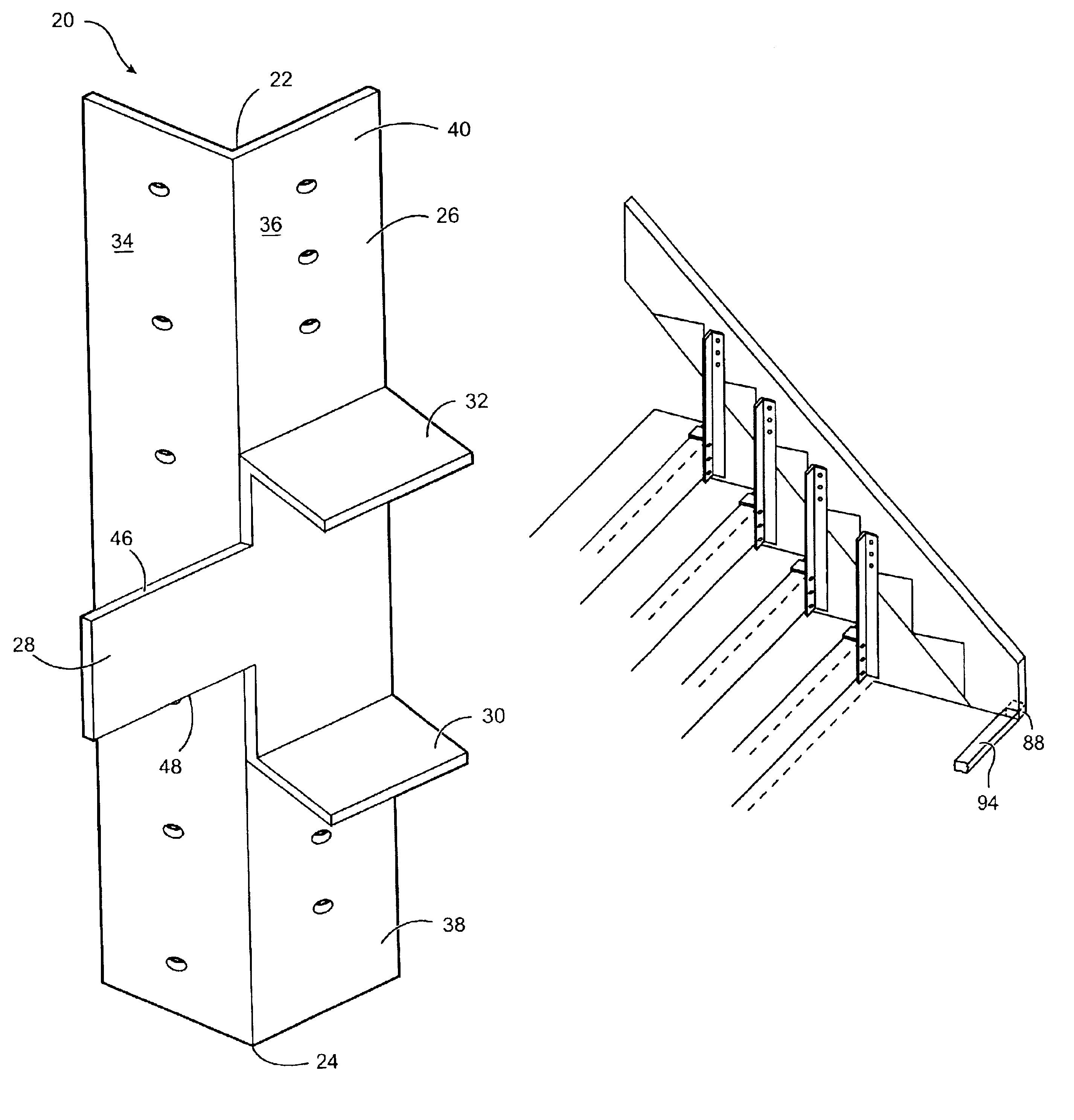
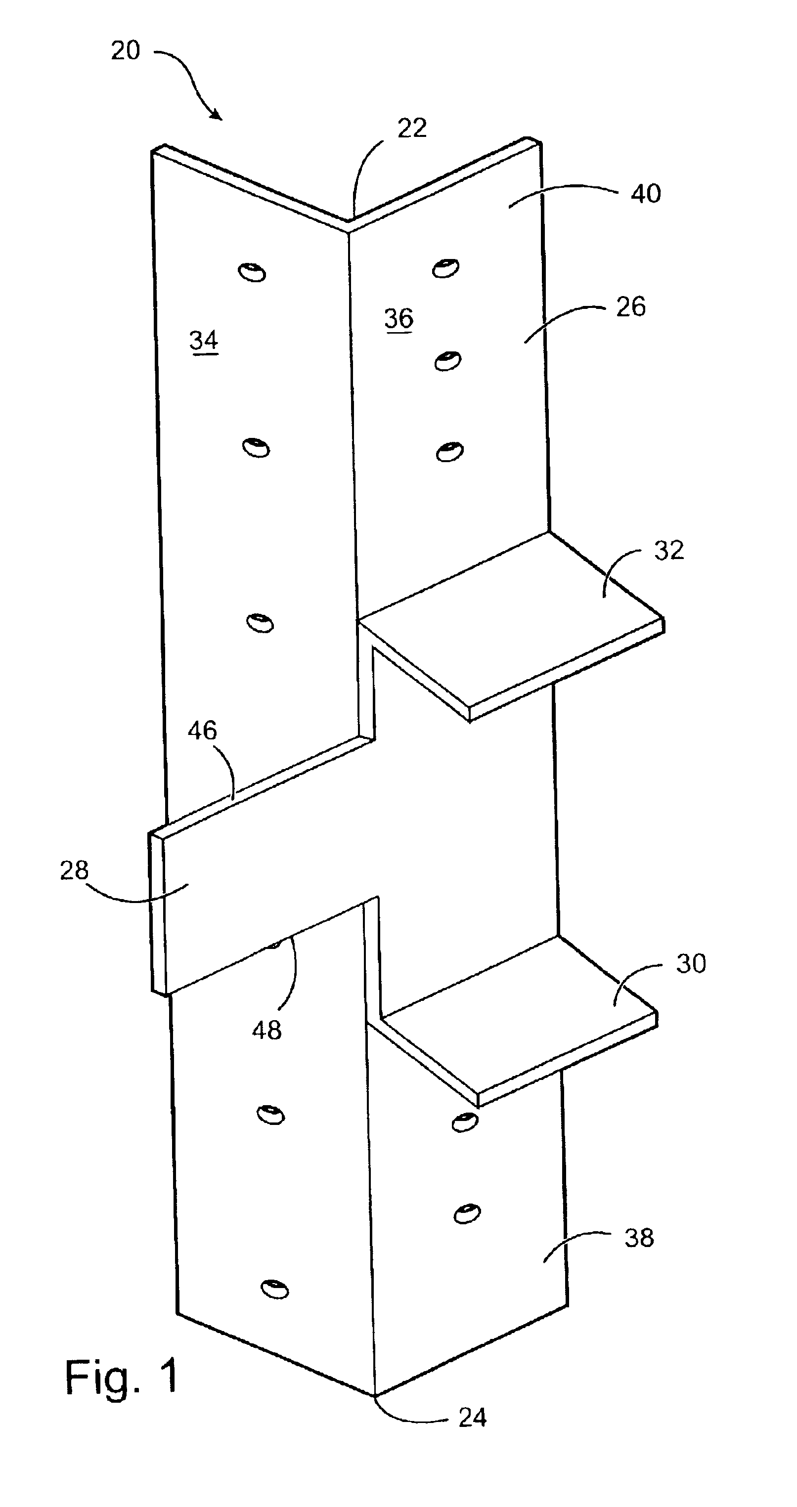
Referring now to the drawings, FIG. 1 shows an apparatus 20 according to the present invention. The apparatus has a first end 22 opposite a second end 24 of a bracket 26. The apparatus includes the bracket 26, a stringer stop 28, and at least a first riser stop 30. The apparatus may also include a second riser stop 32.

The bracket 26 has a stringer mount face 34 and a riser mount face 36. The riser mount face includes a first mounting region 38 and a second riser mounting region 40. The stringer mount face and the riser mount face extend longitudinally between the first end 22 and the second end 24. At least a portion of the stringer mount face defines a stringer mount plane and at least a portion of the riser mount face defines a riser mount plane. The bracket is configured such that the stringer mount plane is generally perpendicular to the riser mount plane.

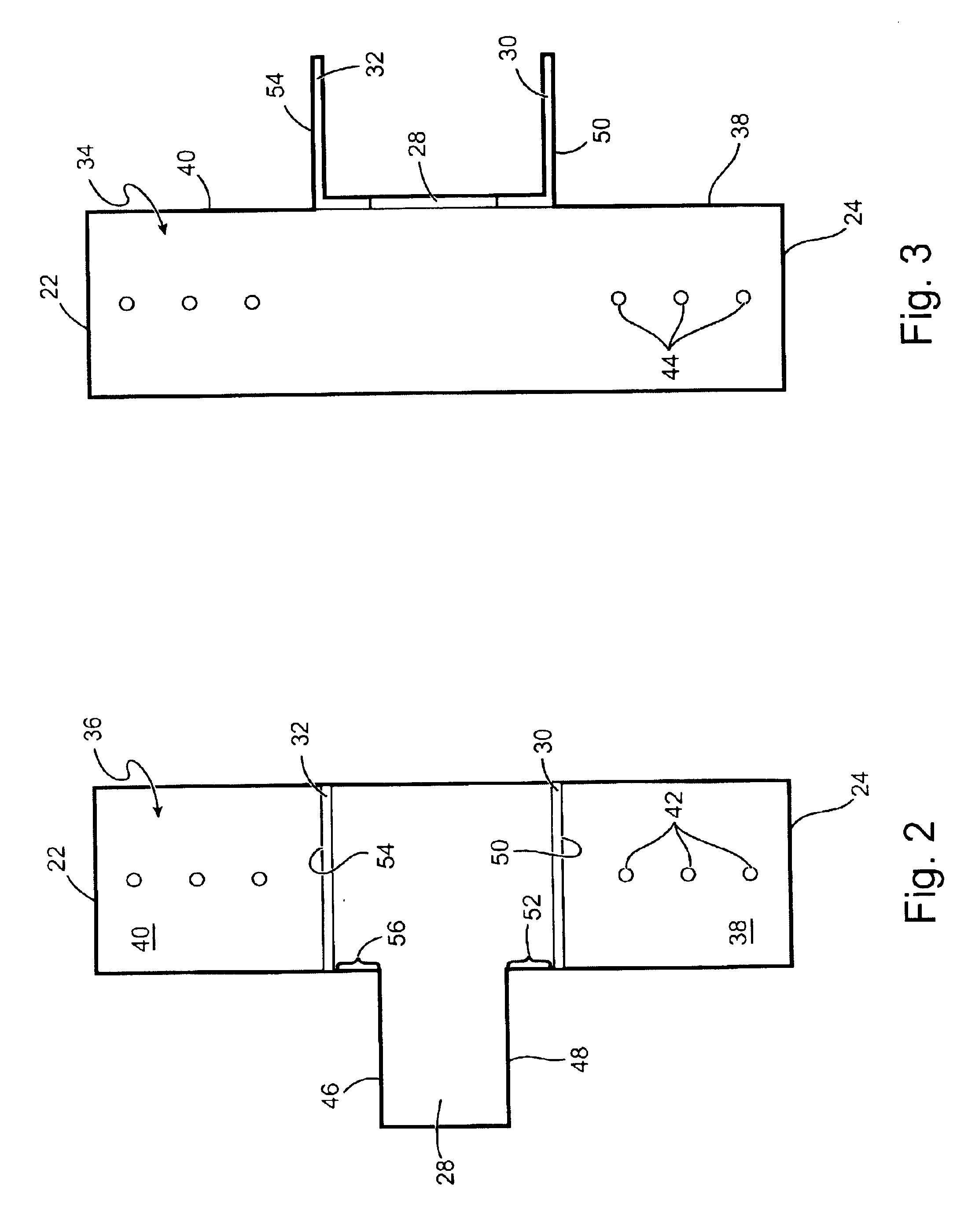
Referring now to FIGS. 2-3 (a side and front plan view respectively of the apparatus of FIG. 1), the riser mount face 36 and ...


PUM

PropertyMeasurementUnit
distanceaaaaaaaaaa
thicknessaaaaaaaaaa
floor elevationaaaaaaaaaa

Abstract

Construction forms for making concrete forms for making stairs have a bracket with a stringer mount face and a riser mount face. Each mount face has mounting structure located thereon. A longitudinally extending stringer stop extends away from and perpendicular to a stringer mount plane in a first direction, the stringer stop having a surface adapted to abut a bottom of a stringer. A laterally extending first riser stop has a first riser abutting surface. The first riser stop extends laterally away from the riser mount face in a second direction and is longitudinally spaced a first distance from the stringier stop. The second direction is perpendicular to the first direction. The first riser abutting surface is adapted to abut a top of a riser. Use of the bracket in an assembly with a stringer and a riser are also disclosed.

Description

SUMMARY OF THE INVENTIONThe present invention relates to construction forms and more specifically to a device for making concrete forms for making stairs. Pouring concrete requires a form to hold the liquid concrete until it can dry to its solid form. The top surface of the wet concrete is left open to allow excess material removal. Creating a form to pour stairs involves securing a set of risers to a set of stringers. The risers contain the wet concrete and when removed correspond to the rise of each step. The top surface of the wet concrete hardens to form the tread of each step. Currently, a stair form is created by cutting portions out of a piece of wood (see FIGS. 8-9). Removing the outline of the stairs, including the thickness of the risers and a finishing space, forms a stringer. The stringer is then hung in place by anchoring at a floor elevation and securing at a landing elevation. Additional stringers are added at regular intervals between the right and left sides of the ...

Claims


Application Information

Patent Timeline
Patent Type & Authority Patents(United States)
IPC IPC(8): E04G13/00E04G13/06
CPCE04G13/06Y10T29/49895E04G13/062
Inventor RELLERGERT, LEROY J.
Owner RELLERGERT LEROY J
Why Eureka
Try Eureka