End connector assembly

a technology of end connectors and assembly parts, which is applied in the direction of couplings, manufacturing tools, building scaffolds, etc., can solve the problems of inconvenient, time-consuming and difficult for a person to remove a gas spring end connector assembly, and difficulty in removing ball studs, so as to achieve the effect of reducing effort and tim

Inactive Publication Date: 2005-03-01
ARVIN TECH INC
View PDF16 Cites 12 Cited by
  • Summary
  • Abstract
  • Description
  • Claims
  • Application Information

AI Technical Summary

Benefits of technology

In principal aspects, the improved end connector assembly of the present invention allows for the body of the connector assembly to be connected with, disconnected from and re-connected with the ball on a ball stud with a minimum of effort and time and by moving the connector assembly along a path generally aligned with or parallel with the longitudinal axis of the gas spring, that is, the longitudinal axis of the gas spring s

Problems solved by technology

The structures of currently available gas spring connector assemblies make it inconvenient, time consuming and difficult for a person to remove a gas spring end connector assembly from a ball stud.
Having t

Method used


Image

  • End connector assembly
  • End connector assembly
  • End connector assembly

Examples


Embodiment Construction

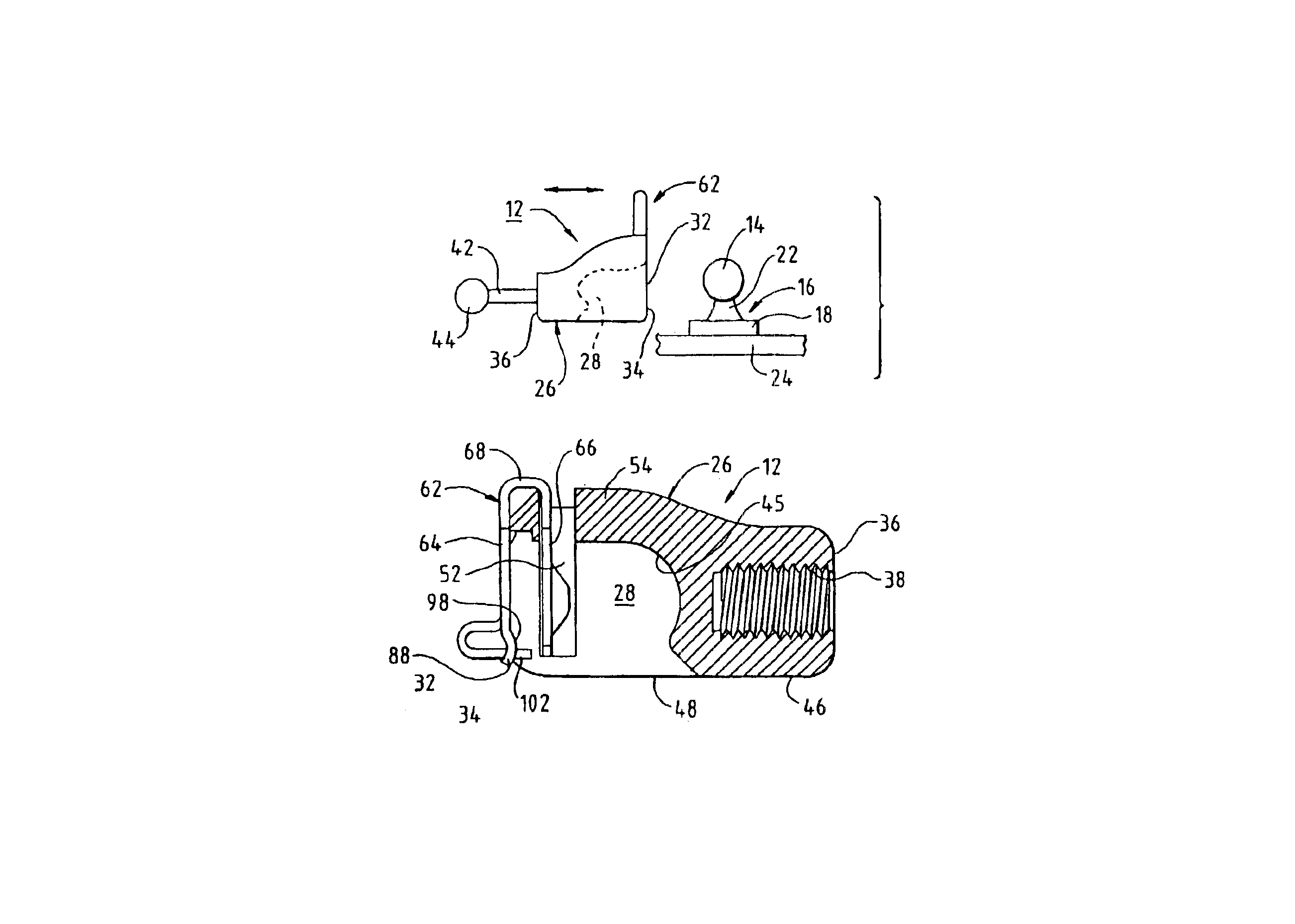
Referring now to FIG. 1, an end connector assembly 12 of the present invention is shown in a position where the assembly 12 is able to be readily connected with a ball 14 that is on the end of an integral ball stud 16. The ball 14 has a predetermined diameter and is supported on a base portion 18 of the ball stud 16 by a shaft portion 22. The ball stud 16 is secured to a relatively fixed surface 24 that may, for example, be a part of the bed of the pickup truck.

The assembly 12 includes a connector body or housing 26 that has a ball receiving socket cavity 28. The connector body 26 is preferably zinc die cast but, of course, could be made of other suitable materials and methods, such as from a strong, moldable plastic material.

An opening 32 (or first opening) in the front or first surface 34 of the connector body 26 has a size and shape and is dimensioned so as to permit the ball 14 to easily pass through the opening 32 and into or from the socket cavity 28. A rear surface 36 of the ...


PUM


Abstract

The end connector assembly (12) for a gas spring (44) enables the connector body to be connected with and disconnected from a ball (14) on the end of a ball stud (16) by relatively moving the connector body (26) and ball along a path generally parallel with the longitudinal axis of the gas spring (44) to which the connector body (26) is connected. The ball (14) enters the connector body (26) through an opening (32) in the body's front surface, that is, the surface generally perpendicular to the gas spring's longitudinal axis. A slot in the body's bottom surface, that is, the surface facing the ball (14), accommodates the shaft portion (22) of the ball stud (16), adjacent the ball (14), as the ball moves into or out of the connector body (26) through the opening (32). A retainer clip is connected with the connector body (26) and is selectively movable between a first or open position where the ball may be admitted into or withdrawn from the connector body (26) and a second or closed position where the ball is secured within the connector body by the retainer clip (62).

Description

BACKGROUND OF THE INVENTIONThe present invention relates to end connector assemblies that are adapted to be connected with and disconnected from the ball of a ball stud, and more particularly, to end connector assemblies that are adapted for use with gas springs employed in automotive applications.End connector assemblies have been used for years in many applications. These assemblies have been and are utilized to mechanically interconnect relatively movable parts. Increasingly, such assemblies have been employed for use with gas springs in the automotive field, where the gas springs are utilized to control the positioning of relatively movable parts. Examples of end connector assemblies, which are usable in automotive applications, are disclosed in U.S. Pat. Nos. 5,372,446; 5,417,512; and 5,676,484. The disclosures of these patents are incorporated herein by reference.In end connector assemblies currently being used with gas springs in automotive applications, the ball of a ball st...

Claims


Application Information

Patent Timeline
IPC IPC(8): F16C1/14F16C11/06F16C1/10B60R5/04A61M39/00F16B21/07F16B21/12
CPCF16C1/14F16C11/069F16C2361/53Y10T403/32811Y10T403/587Y10T403/7176Y10T403/32631Y10T403/32737Y10T403/32803F16B2200/71
Inventor JEFFRIES, MARK S.
Owner ARVIN TECH INC
Why Eureka
Try Eureka