Fan with collapsible blades, redundant fan system, and related method

a technology of collapsible blades and fan systems, applied in the direction of instruments, marine propulsion, vessel construction, etc., can solve the problems of inability to meet the needs of the user, improper performance or even permanent damage to the computer, and increase the cost of the user, so as to reduce the inefficiency of the fan and prevent undesirable blockage of the air stream

Inactive Publication Date: 2005-03-01
NIDEC AMERICA CORP
View PDF16 Cites 265 Cited by
  • Summary
  • Abstract
  • Description
  • Claims
  • Application Information

AI Technical Summary

Benefits of technology

One aspect of the present invention is directed to a fan having collapsible fan blades and a system and method employing the collapsible fan for providing redundant airflow in a manner that reduces the fan inefficiency caused when one fan in a series mounted pair is not operating, either because it is free-wheeling or in a locked rotor condition. The first or collapsible fan includes collapsible blades that open due to centrifugal motion when the fan is operating. If and when the first fan ceases to operate, either because of mechanical or electrical failure or otherwise, the second fan can be energized. Energizing the second fan creates an airflow that forces the collapsible blades of the first fan to fold inward and prevent undesirable blockage of the air stream by the blades of the non-operational fan. In accordance with another aspect of the present invention, the collapsible blades angularly overlap one another such that the leading edge of one blade angularly overlaps the trailing edge of an adjacent blade.

Problems solved by technology

When fans fail, internal temperatures rise, which at the least necessitates shutting down the computer and replacing the failed fan.
At the worst, the fan failure goes unnoticed by support personnel, causing improper performance or even permanent damage to the computer.
In either case, productivity decreases and cost increases.
In this age of smaller and smaller computers, however, space is at a premium, and every fan added means larger computers, higher costs, and less space for other components.
Fans installed in a parallel configuration take up significantly more room than a single fan alone, and the installation of the second fan may not be in a location that allows for optimal airflow over the computer components.
Fans installed in series suffer from different problems.
If one fan is not functioning, the other fan would be operating less efficiently, trying to move air past the non-operational fan.
If the non-operational fan is in a free-wheeling condition (i.e., spinning due to airflow over the blades), efficiency of the operational fan is still reduced.
A locked-rotor condition in the non-operational fan poses an even greater obstacle to proper airflow.
These conditions also may lead to reduced fan life for the operational fan.
The solution to this problem would be to remove the non-operational fan from the path of the airflow, but this solution is not practical.
Another drawback associated with current tube axial fans is that the number of blades that can be formed on a given fan is limited by the construction of, and processes used to manufacture such fans.
Otherwise, the manufacturing process would require overly complex and / or expensive molding equipment that would render the fan commercially impractical.
Accordingly, it has been considered impractical to injection mold rotor hub and blade assemblies with overlapping blades.
However, this manufacturing process is believed to be relatively expensive and therefore undesirable in comparison to the processes used to injection mold conventional tube axial rotor hub and blade assemblies.
None of these fans, however, address the problem of reduced fan efficiency in series mounted fans in the event of a fan failure.
Similarly, none of the existing collapsible fans address the problem of continuously operating a computer or other electronic apparatus (e.g., communications equipment, appliances, and automotive equipment) in the event of a fan failure.

Method used


Image

  • Fan with collapsible blades, redundant fan system, and related method
  • Fan with collapsible blades, redundant fan system, and related method
  • Fan with collapsible blades, redundant fan system, and related method

Examples


Embodiment Construction

The currently preferred embodiments of the present invention overcome many of the problems that arise when fan systems that are used in computers and other electronic applications fail. The advantages, and other features of the disclosed fan, system and method, will become more readily apparent to those having ordinary skill in the pertinent art from the following detailed description of certain preferred embodiments taken in conjunction with the drawings which set forth representative embodiments of the present invention and wherein like reference numerals identify similar structural elements.

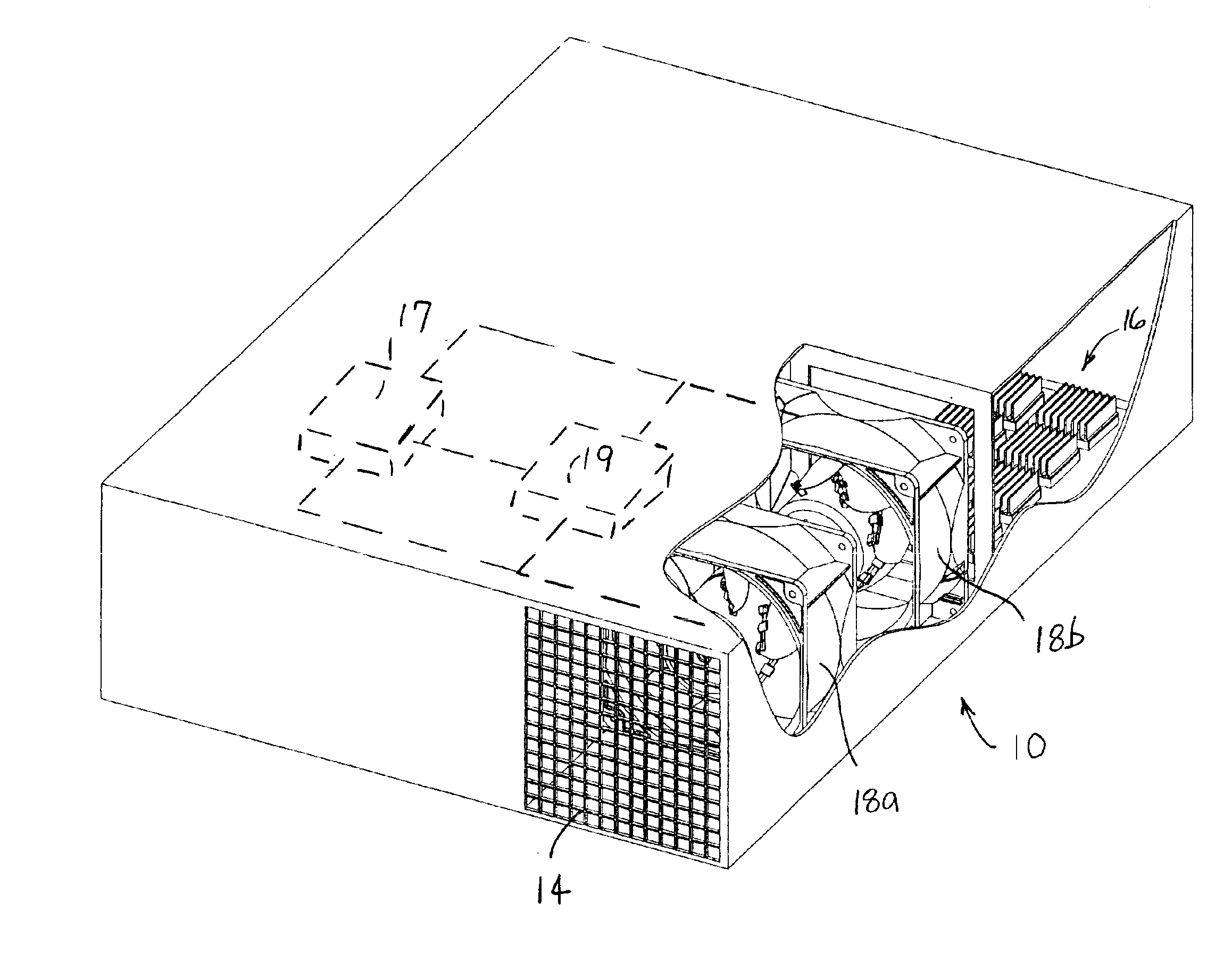
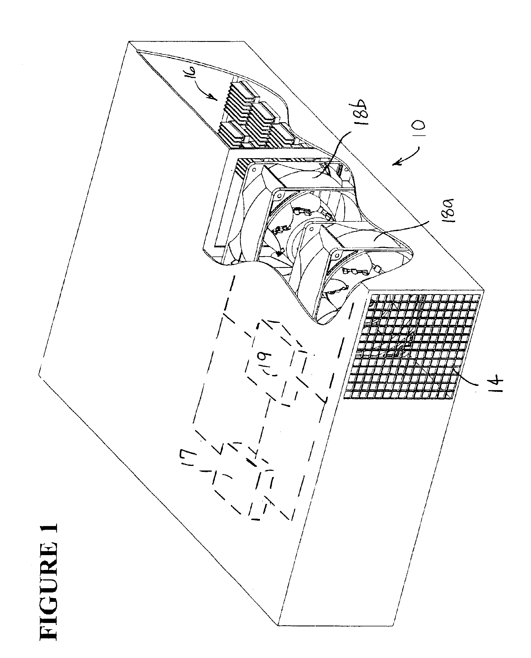
In FIG. 1, numeral 10 generally refers to a computer having a computer housing 12 served by a redundant fan system. The computer housing 12 defines at least one opening 14 and contains a number of computer components 16 (e.g., transformers, processors, circuitry, integrated circuits, power supplies, or like elements). A redundant fan system of the present invention includes a first fan 18a and...


PUM


Abstract

A redundant fan system for a computer includes two fans installed in series with at least one of the fans having collapsible blades. A fan system of this type reduces the fan inefficiency caused when one fan in a series mounted pair is not operating, either because it is free-wheeling or in a locked rotor condition. When non-operational, the fan blades of the collapsible fan fold inward due to airflow generated by the operational fan over the collapsible blades. The ability of the blades to fold reduces the inefficiency of the operational fan, having less of an effect on fan life. Also, because the flow of air is less restricted, proper airflow can be maintained, thus preventing overheating of the computer.

Description

FIELD OF THE INVENTIONThe present disclosure relates to fans having collapsible blades and redundant airflow systems that employ fans with collapsible blades. The present disclosure further relates to systems that can provide redundant airflow in a variety of applications, including computers, electronic communications, appliances and automotive applications, while reducing the problem of fan inefficiencies that are present when a non-operational fan is in an inoperative locked rotor or free-wheeling condition.BACKGROUND INFORMATIONFans are critical components of computers, providing cooling airflow to processors, microchips, and other components. When fans fail, internal temperatures rise, which at the least necessitates shutting down the computer and replacing the failed fan. At the worst, the fan failure goes unnoticed by support personnel, causing improper performance or even permanent damage to the computer. In either case, productivity decreases and cost increases. In addition...

Claims


Application Information

Patent Timeline
Patent Type & Authority Patents(United States)
IPC IPC(8): F01D5/00G06F1/20
CPCF01D5/00G06F1/20F05D2270/11F05B2240/202H05K7/2019F04D29/362H05K7/20172H05K7/20718F04D19/007F04D27/008F04D29/382
Inventor HOOVER, JOHN
Owner NIDEC AMERICA CORP
Why Eureka
Try Eureka