
Active vibration attenuation

Inactive Publication Date: 2005-03-01
ASM TECH SINGAPORE PTE LTD
View PDF9 Cites 10 Cited by
  • Summary
  • Abstract
  • Description
  • Claims
  • Application Information

AI Technical Summary

Benefits of technology

It is therefore an objective of the invention to seek to provide an apparatus and method for vibration attenuation such that the effects of reaction forces caused by an object being moved are reduced substantially concurrently with the generation of such reaction or vibrational forces.

Problems solved by technology

As a result, the reaction force received by the motor, if sufficiently large, causes vibration or shock to the machine.
Vibration and shock are undesirable and will affect machine performance, especially in the semiconductor industry where speed and precision are important.
However, reaction forces created by the driving movement acts on the motor and motor platform, causing vibration of the same.
Thus, precision may be sacrificed at the expense of speed if such vibration is not attenuated.
However, since the body of the motor is no longer rigidly fixed, there is a need for more critical control requirements and complicated control algorithms.
However, a drawback of the device described therein is that it requires a vibration sensor to sense the vibrations of a vibrating surface before the vibrations are processed by a processing unit to produce a suitable feedback.
This solution is not sufficiently responsive where vibration forces are continually changing, and there is not sufficient time to sense an amount of vibration before seeking to counteract such vibration.

Method used


Image

  • Active vibration attenuation
  • Active vibration attenuation
  • Active vibration attenuation

Examples


first embodiment

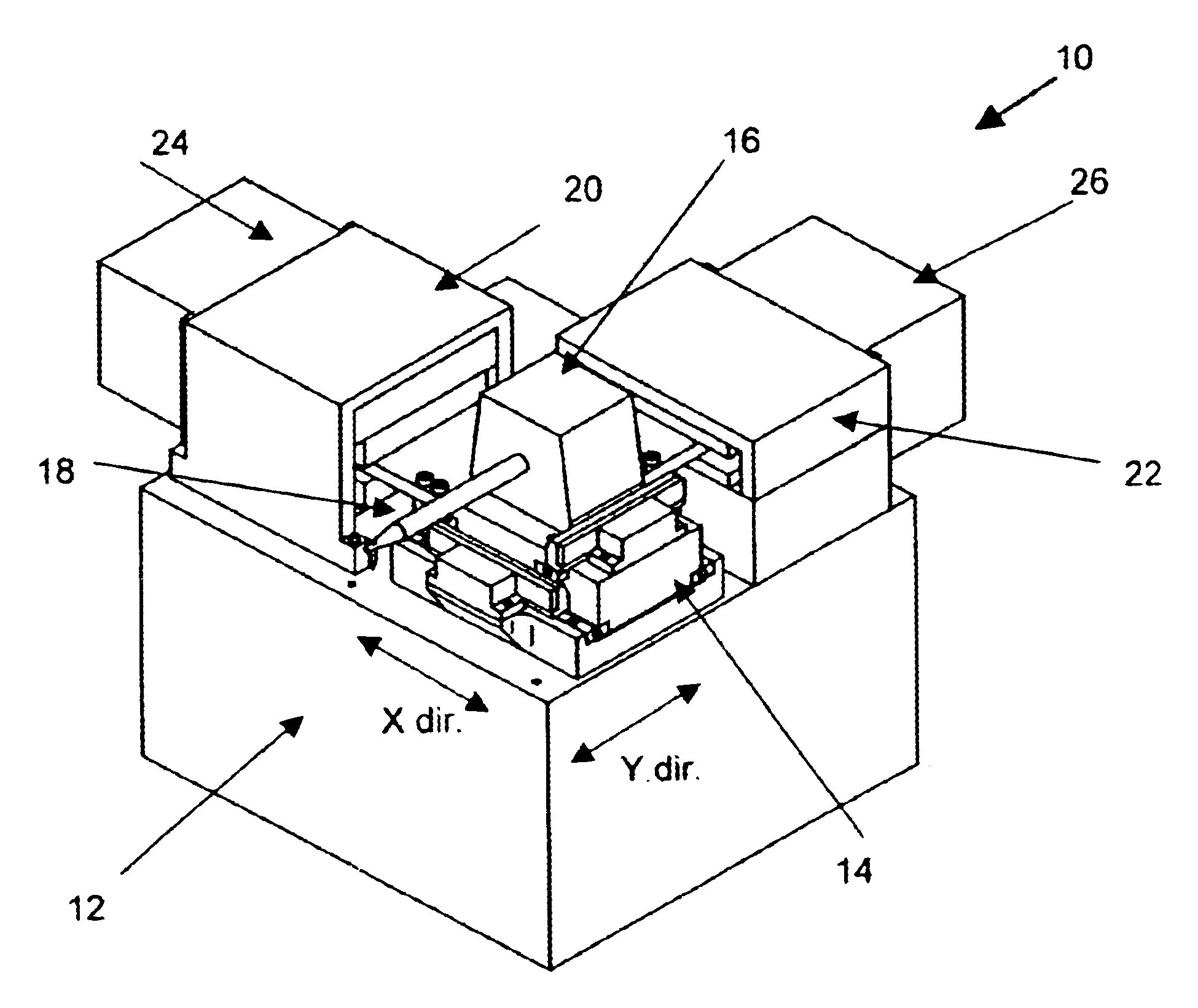
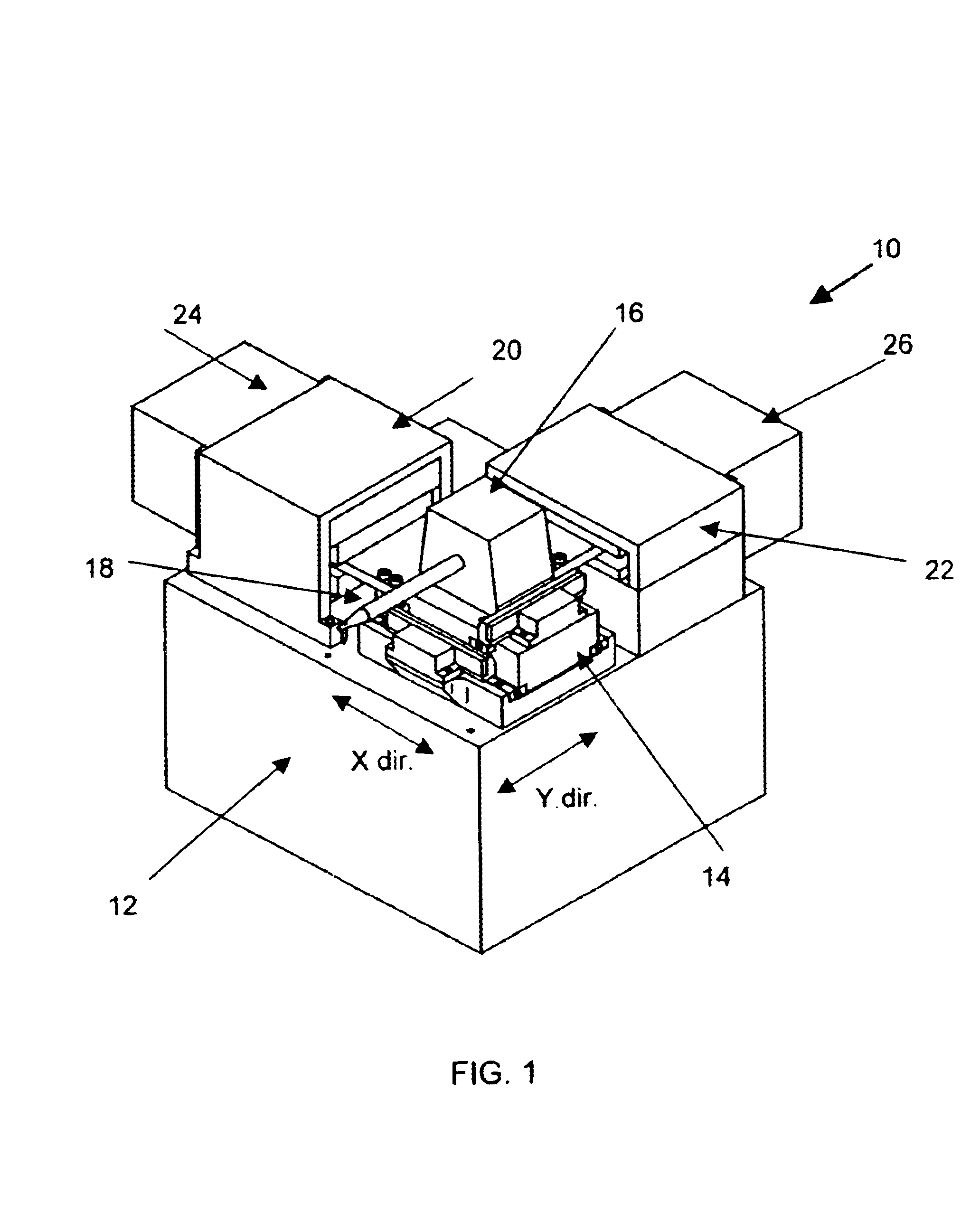
According to the invention, an X attenuation actuator 24 is attached to the X motor 20 and a Y attenuation actuator 26 is attached to the Y motor 22. The function of the attenuation actuators 24, 26 is to generate a force that opposes the reaction force acting on each of the respective motors 20, 22, that is, in a direction that is opposite to the reaction force. Ideally, the value of the attenuation force is substantially equal to the reaction force, but if that is not possible due to design requirements, the value of the attenuation force may be a portion of the reaction force instead. It is possible to generate an attenuation force that is substantially equal to the reaction force because the reaction force is equal in value to the driving force from the respective motors 20, 22, which is known or determinable. The attenuation actuator 24, 26, is thus designed to produce a force that is essentially equal to the driving force, but mechanically decoupled from the driving force.

second embodiment

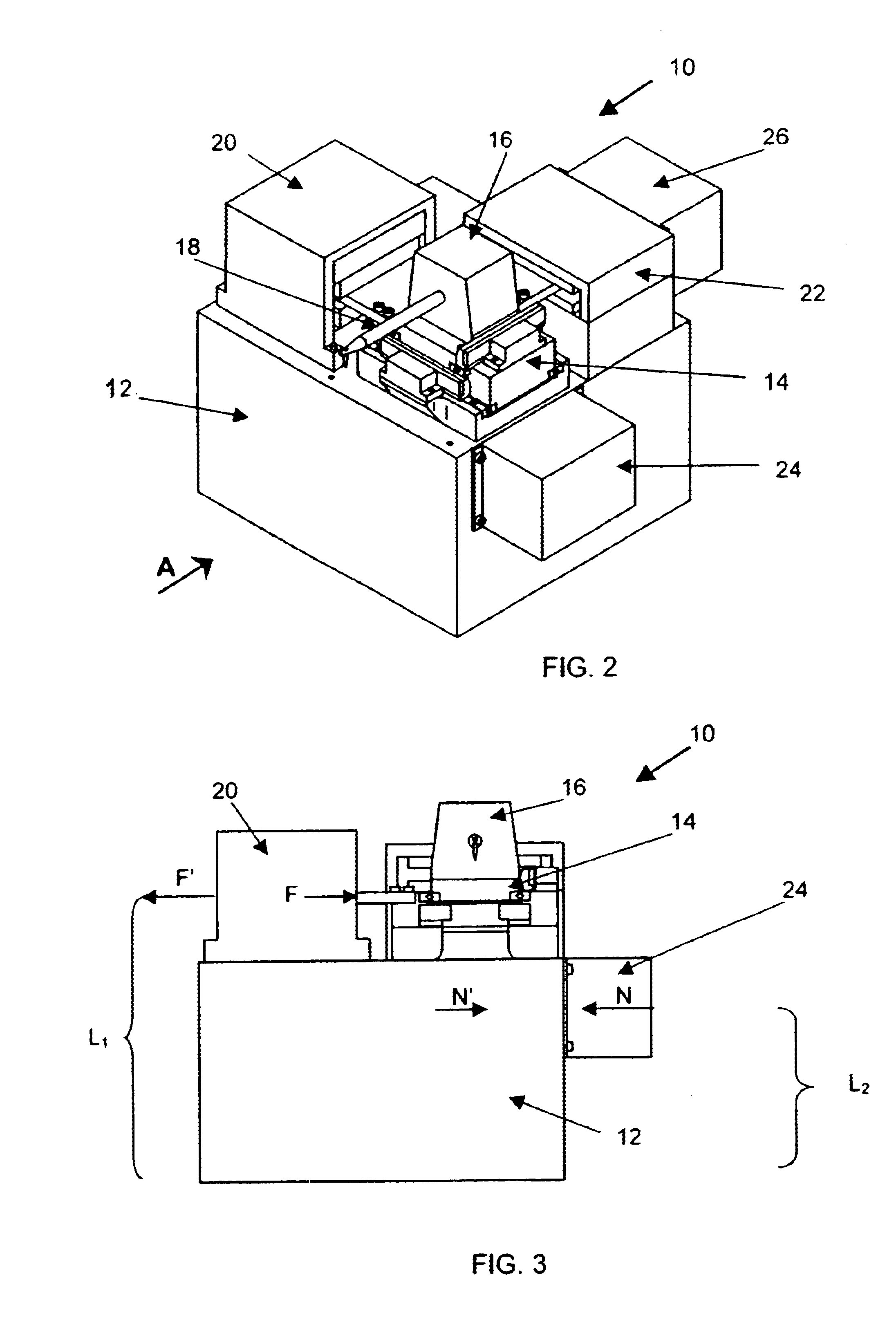
FIG. 2 is an isometric view of the X-Y table 10 incorporating attenuation actuators 24, 26 according to another preferred embodiment of the invention. In this embodiment, the X attenuation motor 24 is attached to the X-Y table base 12 instead of to the X motor 20. This layout may be more desirable or necessary if there is insufficient space next to the X motor 20 for attachment of the X attenuation motor 24, or because of other design considerations. For comparison, the Y attenuation actuator 26 is still attached to the Y motor 26. Mechanically, it is more desirable to locate the attenuation motor 24, 26 in alignment with the driving force of the motors 20, 22, since a resulting turning moment may otherwise be present if the force of the attenuation actuator 24 and the reaction force are not aligned, as will be explained in more detail below. Nevertheless, the effect of the reaction force is still significantly reduced notwithstanding the non-alignment. This second embodiment illust...


PUM

PropertyMeasurementUnit
Forceaaaaaaaaaa
Attenuation coefficientaaaaaaaaaa
Resilienceaaaaaaaaaa

Abstract

An apparatus and method are provided for attenuating vibration when driving an object. The apparatus includes a driving device for generating a driving force to drive the object and an attenuation actuator mounted in reciprocal relationship with the driving device for generating an attenuation force substantially concurrently with the generation of the driving force. The attenuation force is generated so as to oppose and at least partially cancel a reaction force exerted by the object in response to the driving force.

Description

FIELD OF THE INVENTIONThe invention relates to the attenuation or reduction of vibration caused when moving a mass with a motor due to a reaction force in response to the driving force. Such vibration attenuation is achievable by attempting to cancel or reduce the effects of such reaction force concurrently with the generation of a driving force to move the mass.BACKGROUND AND PRIOR ARTAccording to Newton's third law of motion, for every action, there is an equal and opposite reaction. In practical application in an industrial machine, when a motor is activated to move a mass or object, the object exerts a reaction force on the motor equal to the force generated to the object by the motor. This reaction force acts on the motor as well as on parts connected to the motor. As a result, the reaction force received by the motor, if sufficiently large, causes vibration or shock to the machine.Vibration and shock are undesirable and will affect machine performance, especially in the semico...

Claims


Application Information

Patent Timeline
IPC IPC(8): H02K41/035
CPCH01L24/78H02K41/0356H01L2224/78H01L2924/01039H01L2924/00014H01L2924/01033H01L2224/48H01L2224/78301H01L2224/45099H01L2924/00
Inventor ZHAI, BAO NIANKWAN, KA SHING KENNYCHEN, WENOU, GANGLIAO, YOU YONG
Owner ASM TECH SINGAPORE PTE LTD
Learn More