
Imaging method for printing forms

a printing form and imaging method technology, applied in the direction of printing, microlithography exposure apparatus, spacing mechanisms, etc., can solve the problems of inability to achieve the effect of reducing the number of parallel imaging channels

Inactive Publication Date: 2005-03-01
HEIDELBERGER DRUCKMASCHINEN AG
View PDF10 Cites 5 Cited by
  • Summary
  • Abstract
  • Description
  • Claims
  • Application Information

AI Technical Summary

Benefits of technology

[0018]The invention also includes a method for determining the largest possible main field with any given imaging channels that cannot be activated for the inventive method for imaging a printing form. As described above, a short imaging time for the exposure of the surface of a printing form may be achieved particularly by means of a high parallelization, i.e., the simultaneous use of several imaging channels. In the method according to the invention, a strong shortening is achieved by means of the largest possible main field: a parallelization of m imaging channels that can be activated simultaneously, on a laser diode bar with n laser diodes leads to (1 / m) of the time. In other words, a loss of parallelization only leads from (1 / n) of the time of a simple exposure to (1 / m) of the time of the simple exposure. However, (1 / m) of the time of the simple exposure is generally shorter in the case of a failure of several laser diodes, than (1 / l) of the time that is required for the exposure of the entire surface of the printing form to be imaged, if only 1 set of contiguous laser diodes are available. The utilization of the method according to the invention is therefore more advantageous than the simple strategy of utilizing only the still contiguous section of laser diodes capable of being activated. In other words, in the method according to the invention, a larger feed, or a larger number, respectively, of the parallel imaging channels is used in an advantageous manner than in the method of the simple strategy, and therefore a lower total imaging time is achieved.

Problems solved by technology

In following this strategy, any failures or malfunction of further imaging channels results in very short sections of the originally n parallel imaging channels.
This is completely unacceptable in practice.
For economical reasons alone this is not feasible, because the other laser diodes on the bar are generally still functional, and the laser diode bar as a whole has not completely malfunctioned.
As a consequence, this method is cost intensive.
Both documents fail to offer any principal solution for the problem of how to proceed in case one or several imaging channels fail.

Method used


Image

  • Imaging method for printing forms
  • Imaging method for printing forms
  • Imaging method for printing forms

Examples


Embodiment Construction

activated, into the main field and into the auxiliary field,

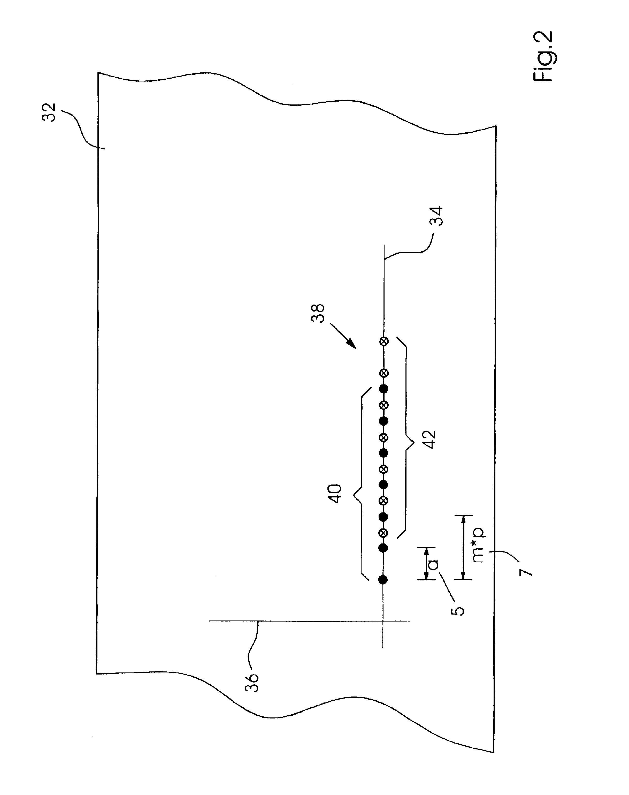
[0036]FIG. 2 a schematic imaging of the position of rows of printing dots on the surface of the printing form,

[0037]FIG. 3 an imaging by means of the auxiliary field of the laser diode bar at a first time of a first part of a first row of printing dots, and an imaging by means of the main field of the laser diode bar at a second time of a second part of the first row of printing dots, and of a first part of a second row of printing dots, and

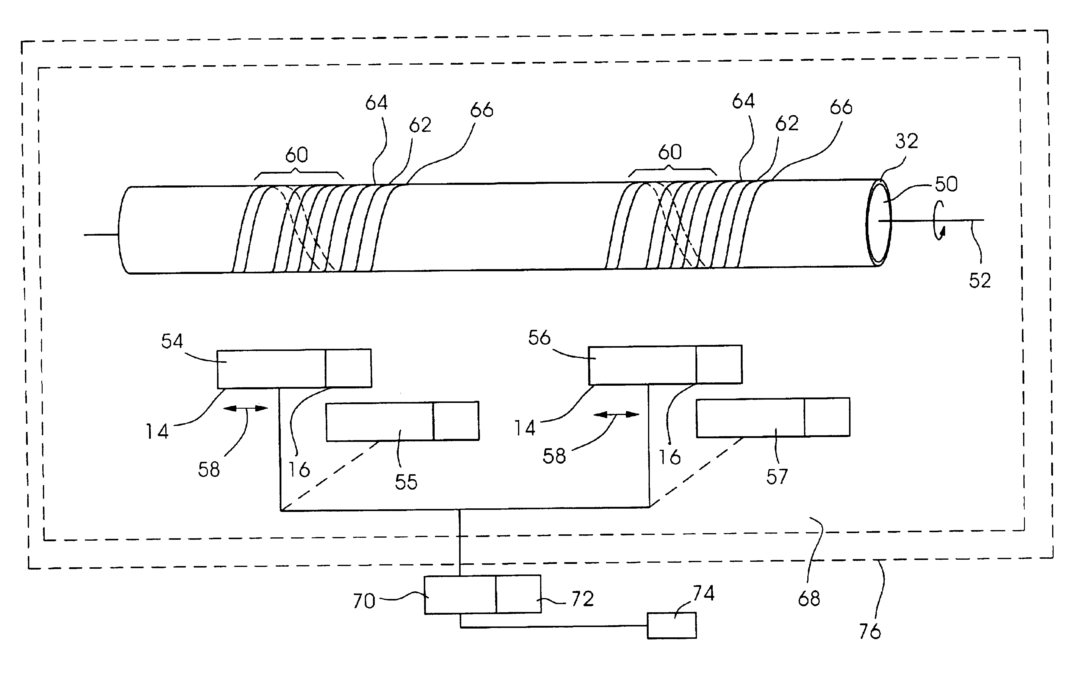
[0038]FIG. 4 two imaging devices with laser diode bars for the imaging of a printing form in a printing unit that is received by a printing form cylinder, whereby the laser diode bars are divided into the main fields and into the auxiliary fields in order to perform an imaging corresponding to the method according to the invention.

DETAILED DESCRIPTION

[0039]FIG. 1 shows divisions of an exemplary laser diode bar, on which the laser diodes are not activated, into the main field and into the...


PUM

PropertyMeasurementUnit
distanceaaaaaaaaaa
time tmaaaaaaaaaa
tmaaaaaaaaaa

Abstract

An imaging method for a printing form (32) is described, with one or more laser diode bars (10) with n individually controllable laser diodes (12) each of which are assigned to one imaging channel, in which the laser diodes (12) of a laser diode bar (10) are divided into a main field (14) of m and into an auxiliary field (16) of (n-m) laser diodes (12) in such a way that an imaging channel (44) in the auxiliary field (16) with a matching feed that can be activated is assigned to each imaging channel (44) in the main field (14) that cannot be activated. In order to create a row (40) of m printing dots (38) on a setting line (36) at even distances a by means of the imaging channels (44), printing dots (38) are set by the main field (14) at a first time, and by the auxiliary field (16) at least at a second time. The imaging channels (44) are shifted relative to the printing form (32) parallel to the setting line (36) between the imaging times. Also, a method for the determination of the largest possible main field (14) with imaging channels (44) that under the circumstances cannot be activated is provided.

Description

[0002]Priority to German Patent Application No. 102 10 308.9, filed Mar. 8, 2002 and hereby incorporated by reference herein, is claimed.BACKGROUND INFORMATION[0003]The invention relates to a method for imaging a printing form with an imaging device which includes a laser diode bar having a number n of individually controllable laser diodes, each of which are assigned to an imaging channel, whereby the imaging spots of the imaging channels are arranged essentially in a row on the printing form. Furthermore, the invention relates to a method for imaging a printing form with a number b of imaging devices each of which includes a laser diode bar, each of which has a number n of individually controllable laser diodes, whereby each laser diode is assigned to an imaging channel, and the imaging spots of the imaging channels of the number b of laser diode bars are arranged essentially in a row on the printing form.[0004]Several imaging channels, especially those equipped with laser diodes,...

Claims


Application Information

Patent Timeline
Patent Type & Authority Patents(United States)
IPC IPC(8): B41J19/16B41J2/455B41J19/00B41C1/10G03F7/20H04N1/036
CPCB41J19/16B41J2/45
Inventor ERNST, UWEVOSSELER, BERND
Owner HEIDELBERGER DRUCKMASCHINEN AG
Learn More