Printer with sheet reversal mechanism

a printing machine and reverse mechanism technology, applied in the field of printing machines, can solve the problems of high cost affecting the operation of the printer, etc., and achieve the effect of preventing a transport failur

Inactive Publication Date: 2005-03-01
SEIKO EPSON CORP
View PDF34 Cites 16 Cited by
  • Summary
  • Abstract
  • Description
  • Claims
  • Application Information

AI Technical Summary

Benefits of technology

to provide a printer which comprises a sheet reversing mechanism, which can perform printing on both faces of a sheet by a common print head, and in which reduction o

Problems solved by technology

In a printer of the type in which print heads respectively for front/back faces are separately disposed, however, a space for disposing the two print heads is necessary, and therefore down-sizing of the printer is obstructed.
Moreover, there is a disadvantage that the number of parts is increased and the cost is high.
In a printer of the type which comprises a mechanism for reversing a whole sheet, the reversing mechanism is a complicated mechanism which reverses a sheet while transferring the sheet among plural rol

Method used


Image

  • Printer with sheet reversal mechanism
  • Printer with sheet reversal mechanism
  • Printer with sheet reversal mechanism

Examples


first embodiment

(First Embodiment)

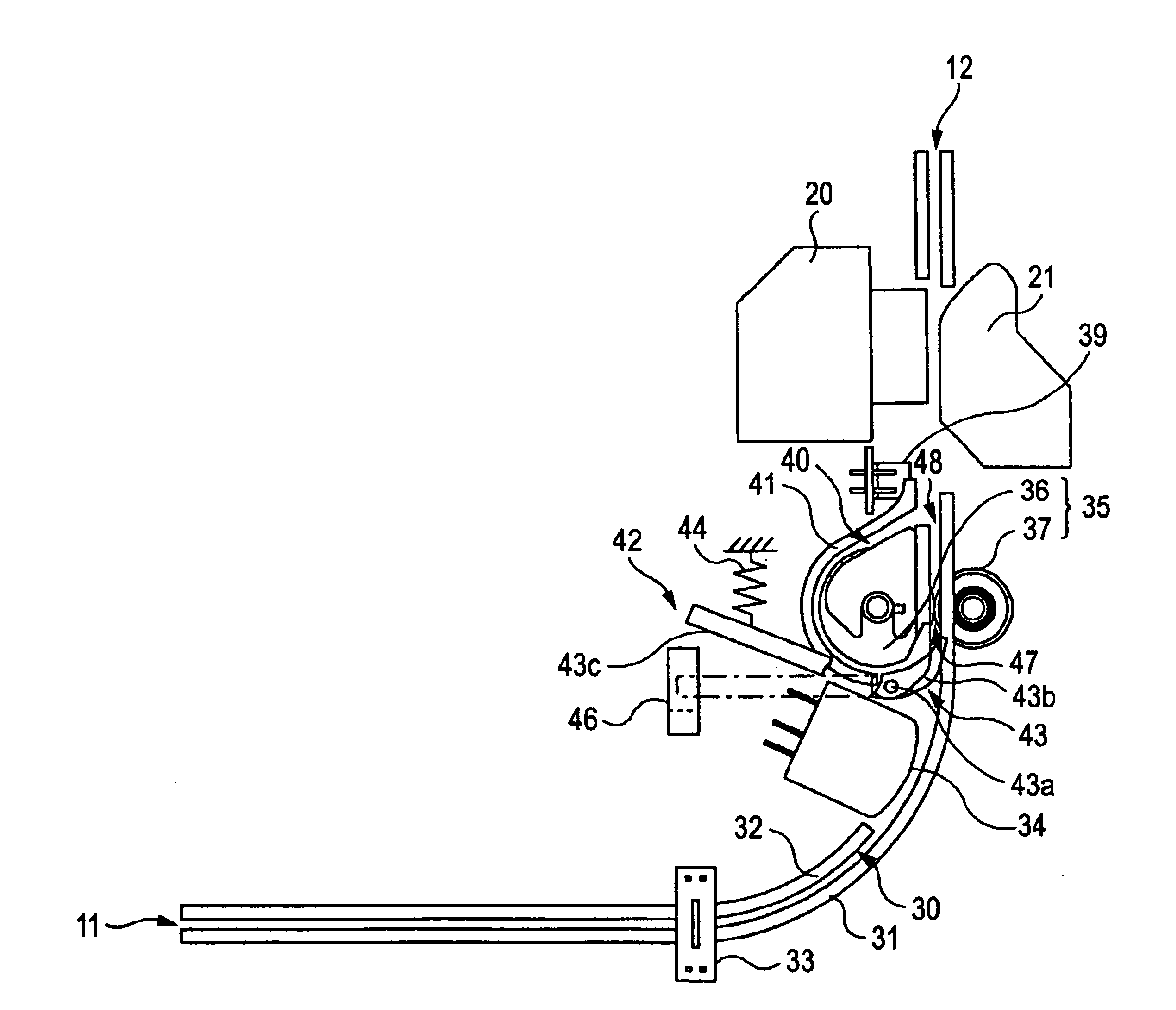
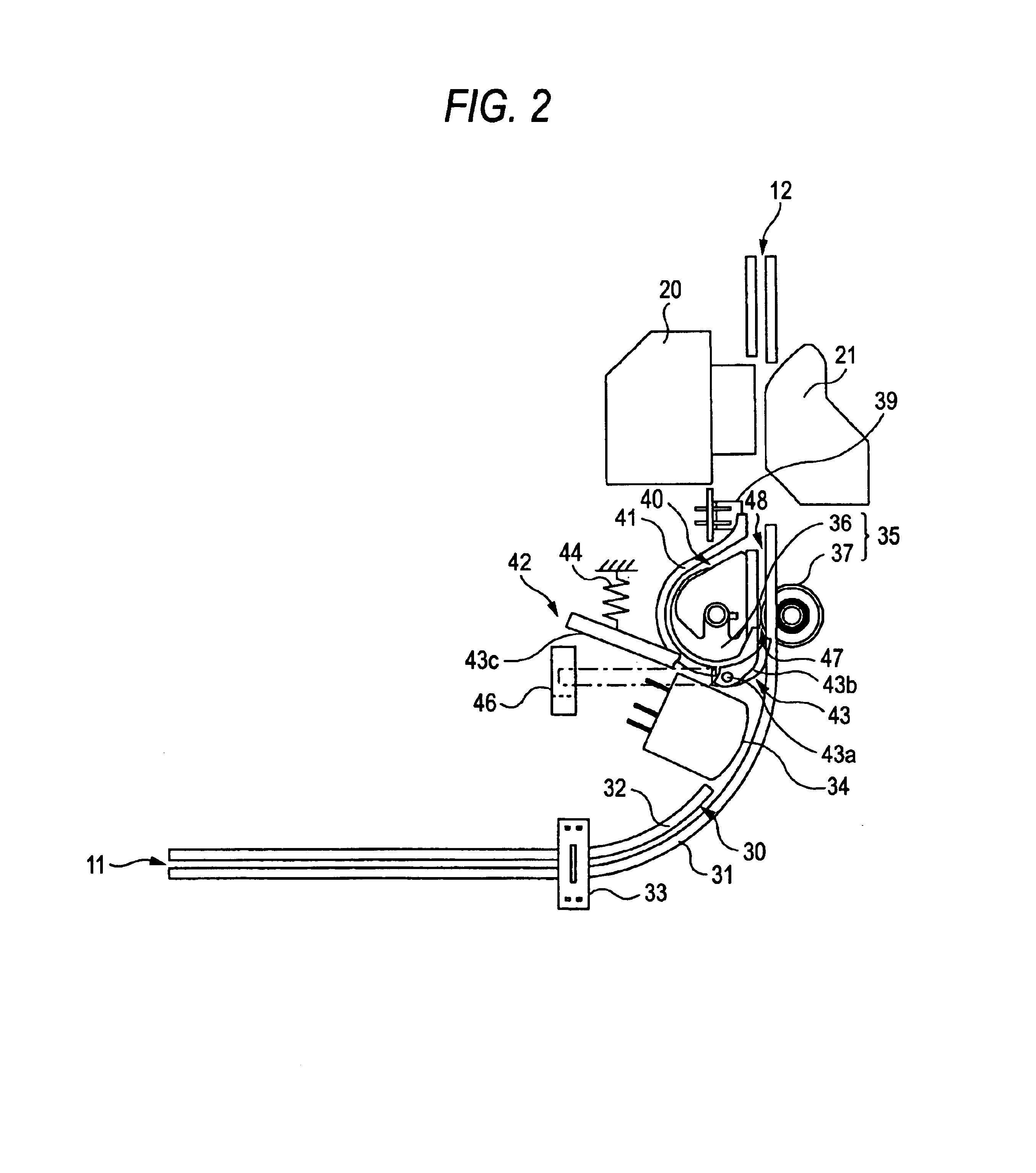
FIG. 2 is a schematic side view showing the inside of a printer according to a first embodiment. In the printer 10, a first sheet path 30 which has a substantially L-like shape in a side view, and which elongates from the cut sheet inlet 11 (hereinafter, often referred to merely as “inlet”) to the cut sheet outlet 12 (hereinafter, often referred to merely as “outlet”) is formed by first sheet guide members 31 and 32. On the first sheet path 30, a first sheet detector 33, a magnetic head 34, the cut sheet transporting roller pair 35 (hereinafter, often referred to merely as “transporting roller pair”), a second sheet detector 39, and the print head 20 are sequentially arranged with starting from the side of the inlet 11.

The first and second sheet detectors 33 and 39 are configured by, for example, photosensors of the transmission type or the reflection type, and detect the existence of the check M in the respective positions of the first sheet path 30. Information s...

second embodiment

(Second Embodiment)

FIG. 12 is a schematic plan view showing the inside of a printer of a second embodiment, and FIG. 13 is a sectional view along X—X and showing the inside of the printer of the second embodiment. In the second embodiment, the press roller 37 is retractable with respect to the driving roller 36, and switchingly operated between a posture in which the press roller 37 presses the check M against the driving roller 36, and that in which the press roller 37 retracts from the driving roller 36 to allow the check M to pass therebetween. The driving roller 36 is disposed at plural places separated by predetermined intervals on a driving roller shaft 56 which is laterally elongated. By contrast, the press roller 37 is disposed at plural places separated by predetermined intervals on a press roller shaft 57 which is elongated in parallel to the driving roller shaft 56 at a rear side thereof. The press roller shaft 57 is disposed on a press roller frame 18 which is pivotable ...

third embodiment

(Third Embodiment)

FIG. 22A is a schematic right side sectional view showing the inside of a printer of a third embodiment, and FIG. 22B is a schematic left side sectional view showing the inside of the printer of the third embodiment. As shown in the figures, the third embodiment is different from the second embodiment in the structure of the reversing guide open / close mechanism 60, the operation lever 63 is urged in a clockwise direction by a tension coil spring 72. The embodiment is different also in the structure of the sheet path switching mechanism 42, or in that, in the state of waiting insertion of the check M, the switching plate 67 is urged by a torsion coil spring 74 to retract from the first sheet path 30 and establish the first sheet path selecting posture. Hereinafter, the sheet path switching mechanism 42 will be described.

FIG. 23 is a schematic perspective view showing the inside of the printer of the third embodiment, FIG. 24 is a schematic plan view showing the insi...


PUM


Abstract

In a printer provided with a sheet reversing mechanism, and which can perform printing on both faces of a sheet by a common print head, reduction of the number of parts, prevention of a transport failure, and the like are realized by reversing the sheet while the sheet is clamped by one transporting roller pair. The printer includes a first sheet path. A print head is disposed on the first sheet path to perform printing on a recording sheet. A transporting roller pair includes a first roller and a second roller, adapted to transport the recording sheet in a first direction approaching the print head (toward an outlet) and a second direction opposed to the first direction (toward an inlet). A second sheet path is branched from the first sheet path at a branching position shifted from the first roller in the second direction, extending along an outer periphery of the first roller, and joined to the first sheet path at a joining position between the transporting roller pair and the print head. A path switcher is disposed in the vicinity of the branching position so as to be placed at a first position for selecting the first sheet path and a second position for selecting the second sheet path, so that a path of the recording sheet transported in the second direction is switched to the first sheet path or the second sheet path.

Description

TECHNICAL FIELDThe present invention relates to a printer which has a sheet reversing mechanism, and which can perform printing on both faces of a sheet by a common print head.BACKGROUND ARTRecently, a printer which can perform printing on both faces of a sheet has been developed. Printers of this kind include: a printer in which print heads respectively for front / back faces are separately disposed, as disclosed in Japanese Patent Publication No. 3-53955A; and that which comprises a mechanism for reversing a whole sheet to enable a single print head to perform double-sided printing, as disclosed in Japanese Patent Publications Nos. 59-31178A and 61-89876A.In a printer of the type in which print heads respectively for front / back faces are separately disposed, however, a space for disposing the two print heads is necessary, and therefore down-sizing of the printer is obstructed. Moreover, there is a disadvantage that the number of parts is increased and the cost is high.In a printer o...

Claims


Application Information

Patent Timeline
IPC IPC(8): B41J13/00B41J3/60
CPCB41J3/60B41J13/009B41J13/0045
Inventor SASAKI, TOSHIYUKI
Owner SEIKO EPSON CORP
Why Eureka
Try Eureka