
Method and system for pseudo-random testing a fault tolerant network

a fault-tolerant network and pseudo-random testing technology, applied in the field of pseudo-random testing a fault-tolerant network, can solve the problems of excessive duplication of activity and inefficiency

Inactive Publication Date: 2005-03-01
EMC IP HLDG CO LLC
View PDF3 Cites 10 Cited by
  • Summary
  • Abstract
  • Description
  • Claims
  • Application Information

AI Technical Summary

Benefits of technology

In another aspect, there is disclosed a system for pseudo-random testing a fault tolerant network to determine the network's response. The system includes at least one host having a plurality of storage units having disk arrays therein, which are connected to the host through adapters and switches. The connections between each storage array and the host are made up of more than one path between the host and each storage array, respectively. An image of the network is established in memory on the host, and the host is programmed for pseudo-randomly selecting failures of at least one path to at least one storage unit on the network, and for restoring an active path to the at least one storage unit on the network, and logging each attempt to establish an active path, including the attempt that first successfully establishes the active path.
Yet more specifically, the host is programmed for attempting to restore each path failure, and for logging all attempts to restore each path failure, up to and including the first successful attempt to restore the path, for each path failure of a plurality of path failures.

Problems solved by technology

As may be appreciated, this results in excessive duplication of activity and is not efficient from a time use perspective since it can take a long time to return to the portion of the sequence that a developer is interested in.

Method used


Image

  • Method and system for pseudo-random testing a fault tolerant network
  • Method and system for pseudo-random testing a fault tolerant network
  • Method and system for pseudo-random testing a fault tolerant network

Examples


Embodiment Construction

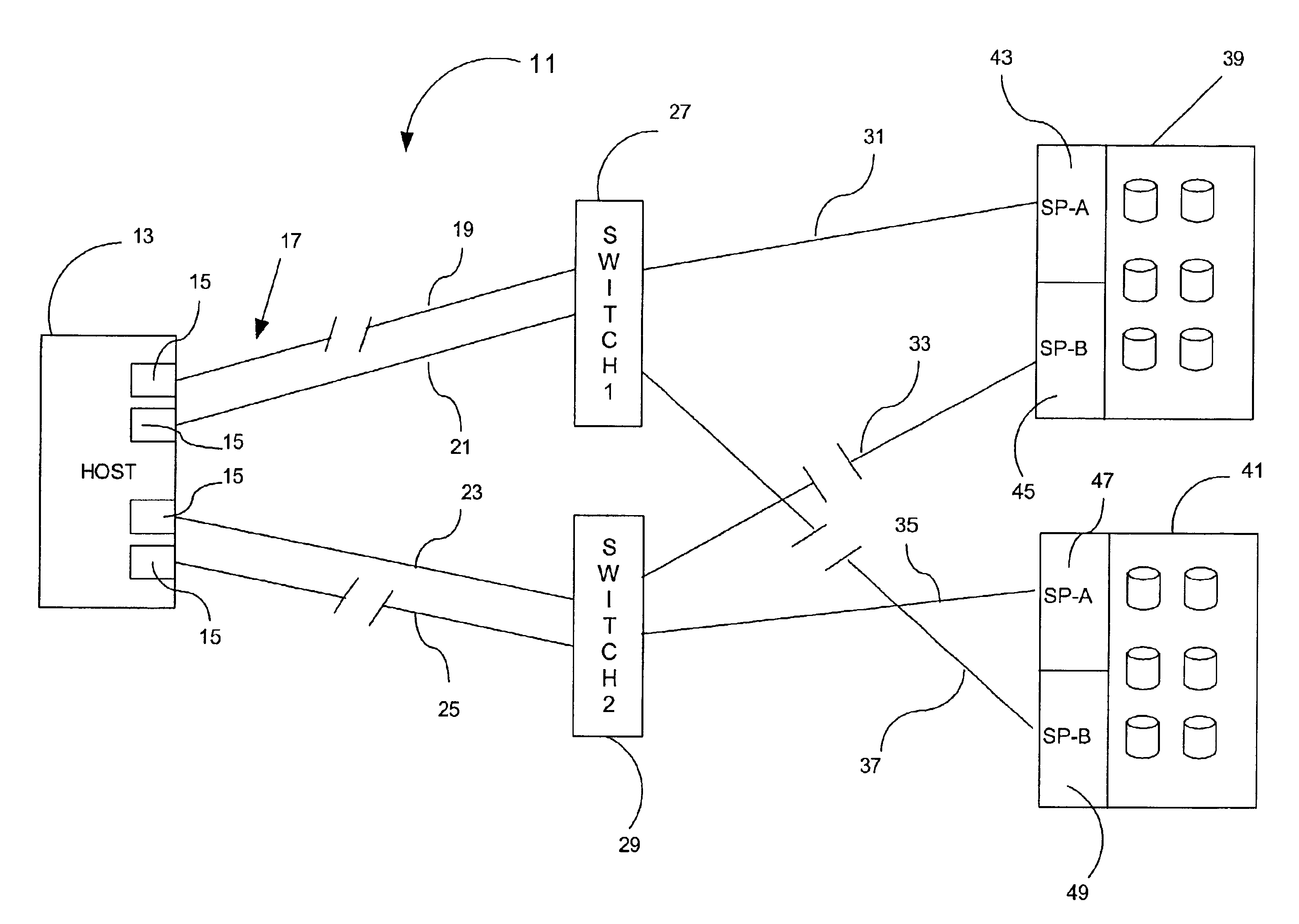
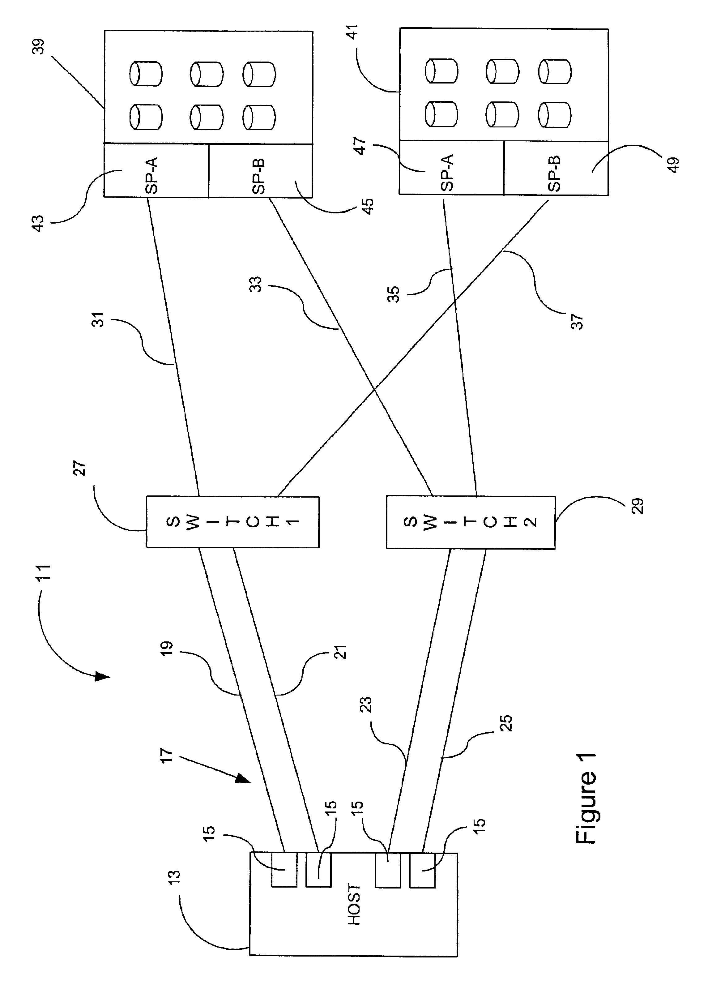
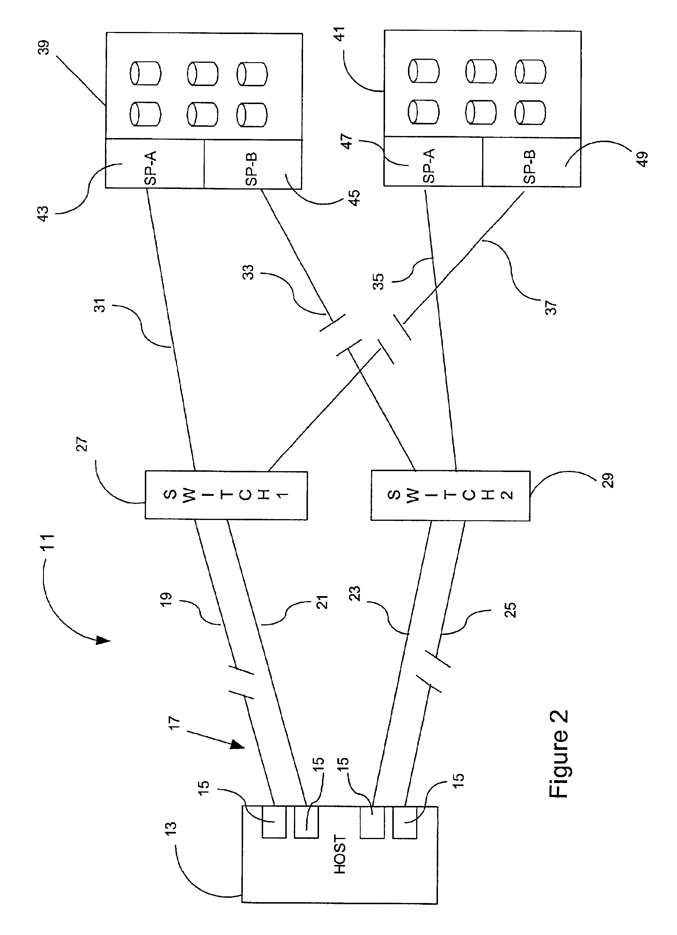
FIG. 1 illustrates a typical network configuration on which the testing method and system in accordance with the description herein is implemented. The network 11 includes a host 13 which can be a server such as from Sun Microsystems, or other type of conventional server running an operating system such as Solaris, DGUX, etc. The server 13 includes a plurality of adapters 15 which are connected through a fibre channel 17 including paths 19, 21, 23 and 25 through switches 27 and 29 to a plurality of storage units housing disk arrays. In this case, for the sake of simplicity the system is illustrated as having only two storage units 39 and 41. The switches establish fibre channel paths 31, 33, 35 and 37 to the storage units 39 and 41 which are controlled respectively by storage processors SP-A and SP-B identified by the numbers 43, 45, 47 and 49. The storage units 39 and 41 include a number of non-volatile memory drives, illustrated in the figure by the cylinders and the operation the...


PUM


Abstract

A method and system for pseudo-random testing a fault tolerant network for determining the network's response to failure includes generating an image of the network on a host. At least one path of the network is selected to be physically failed through the use of a random number generator such that the selection is done pseudo-randomly. The part is then failed and the network's response to the failure is detected and all attempts to repair the failure logged up to and including the first successful attempt to repair the failure. In the event of a failure to repair a path occurs, the test is stopped, a repair effected, and the test restarted at the point the failure to repair occurred.

Description

BACKGROUND OF THE INVENTION1. Field of the InventionThere is disclosed herein a method and system for pseudo-random testing a fault tolerant network to determine the network's response to a failure. More specifically, the method and system discussed herein includes the ability for restarting a pseudo-random sequence in the middle of a sequence.2. Description of the BackgroundPseudo-random testing sequences are used extensively in testing computer software and hardware. More specifically, such testing is done, for example, in a basic fibre channel fabric configuration including at least one host, a fibre channel or multiple fibre channel switches and a plurality of storage arrays connected through the switches to at least one host.In previous pseudo-random testing sequences it has been necessary to start a test over at the beginning of the test in order to reproduce a given sequence for debugging purposes. It has also been necessary to cause the sequence to be exactly repeated throug...

Claims


Application Information

Patent Timeline
Patent Type & Authority Patents(United States)
IPC IPC(8): G06F11/22
CPCG06F11/2273
Inventor MORAN, JOHN M.VOOK, ERIC R.
Owner EMC IP HLDG CO LLC
Learn More