Method of labeling alarms to facilitate correlating alarms in a telecommunications network

a technology of telecommunications network and labeling alarms, applied in the field of data processing, can solve the problems of increasing the total cost of maintaining an oss for a network, creating certain management problems, and difficult isolating new alarms, so as to reduce the cost of oss, reduce the potential for erroneous interpretation of alarms, and simplify the effect of processing efficiency of the oss in parsing unique error messages

Inactive Publication Date: 2005-03-01
CISCO TECH INC
View PDF38 Cites 87 Cited by
  • Summary
  • Abstract
  • Description
  • Claims
  • Application Information

AI Technical Summary

Benefits of technology

[0028]In this arrangement, benefits accrue in that the parsing module to extract correlation keys may be written once and thereby reduce the cost of the OSS. The potential for erroneous interpretation of alarms is reduced because the correlation keys and proxy servers may be tested and

Problems solved by technology

Although this approach has the benefit of ensuring that alarms are known until they are resolved, it also creates certain management problems.
In particular, isolating new alarms is difficult, because the processing required to uniquely identify an alarm is generally equal to the total alarm frequency multiplied by the number of network elements and multiplied by the length of the time period of observation.
Further, these processing requirements, and the associated cost of analyzing the alarm messages, multiplied rib by the number of different software versions or revisions running on each network element or system element, adds significantly to the total cost of maintaining an OSS for a network.
The initial investment of a service provider in an OSS and the cost of upgrading or modifying an OSS are huge, and therefore it is less desirable to upgrade an OSS to read or parse new alarm types that are introduced from time to time.
Still another problem involves propagation of alarms among different network elements.
These approaches have been t

Method used


Image

  • Method of labeling alarms to facilitate correlating alarms in a telecommunications network
  • Method of labeling alarms to facilitate correlating alarms in a telecommunications network
  • Method of labeling alarms to facilitate correlating alarms in a telecommunications network

Examples


Embodiment Construction

of limitation, in the figures of the accompanying drawings and in which like reference numerals refer to similar elements and in which:

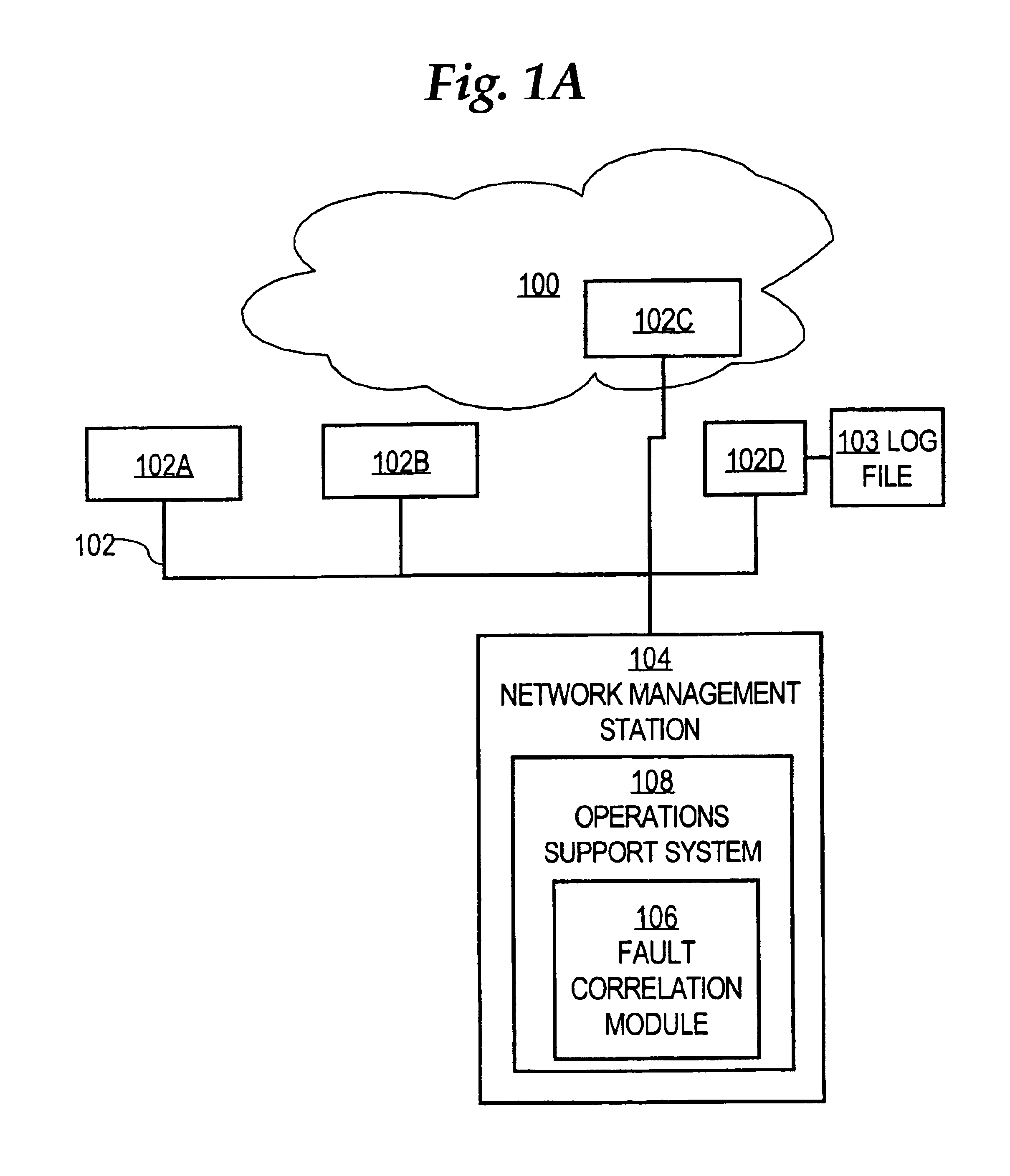
[0034]FIG. 1A is a block diagram of a network context in which fault correlation is carried out in a conventional approach;

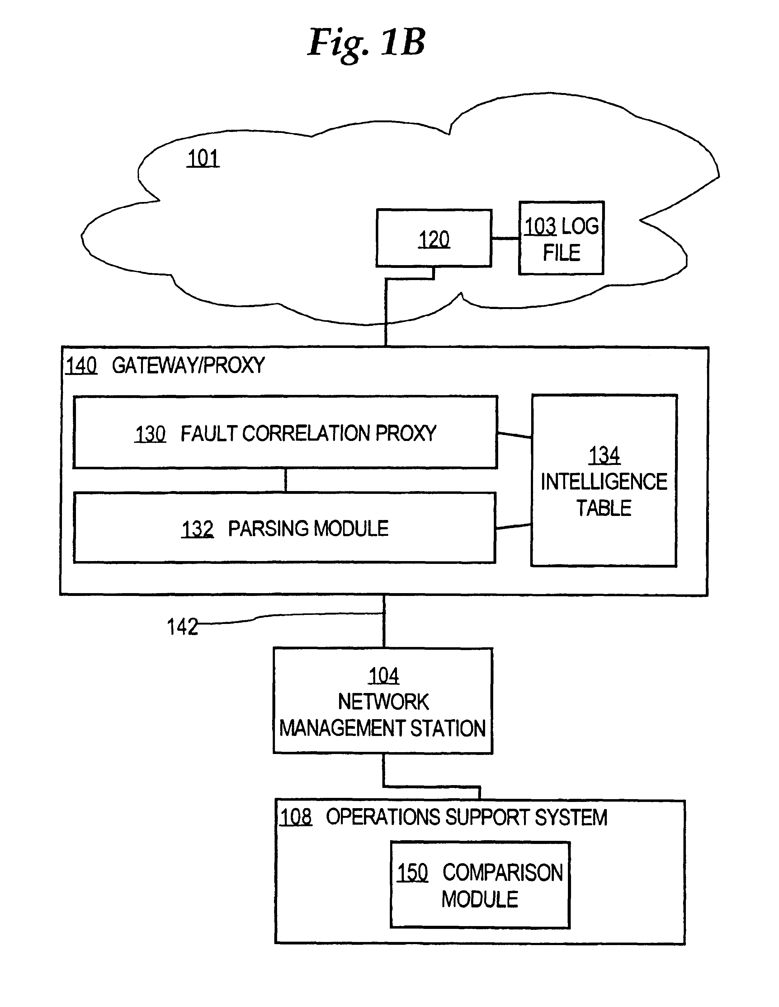
[0035]FIG. 1B is a block diagram of an example network context in which an embodiment may be used;

[0036]FIG. 2 is a block diagram of a network operations support system and its relationship to other logical elements of a network management system;

[0037]FIG. 3 is a block diagram of an intelligence table, in one embodiment;

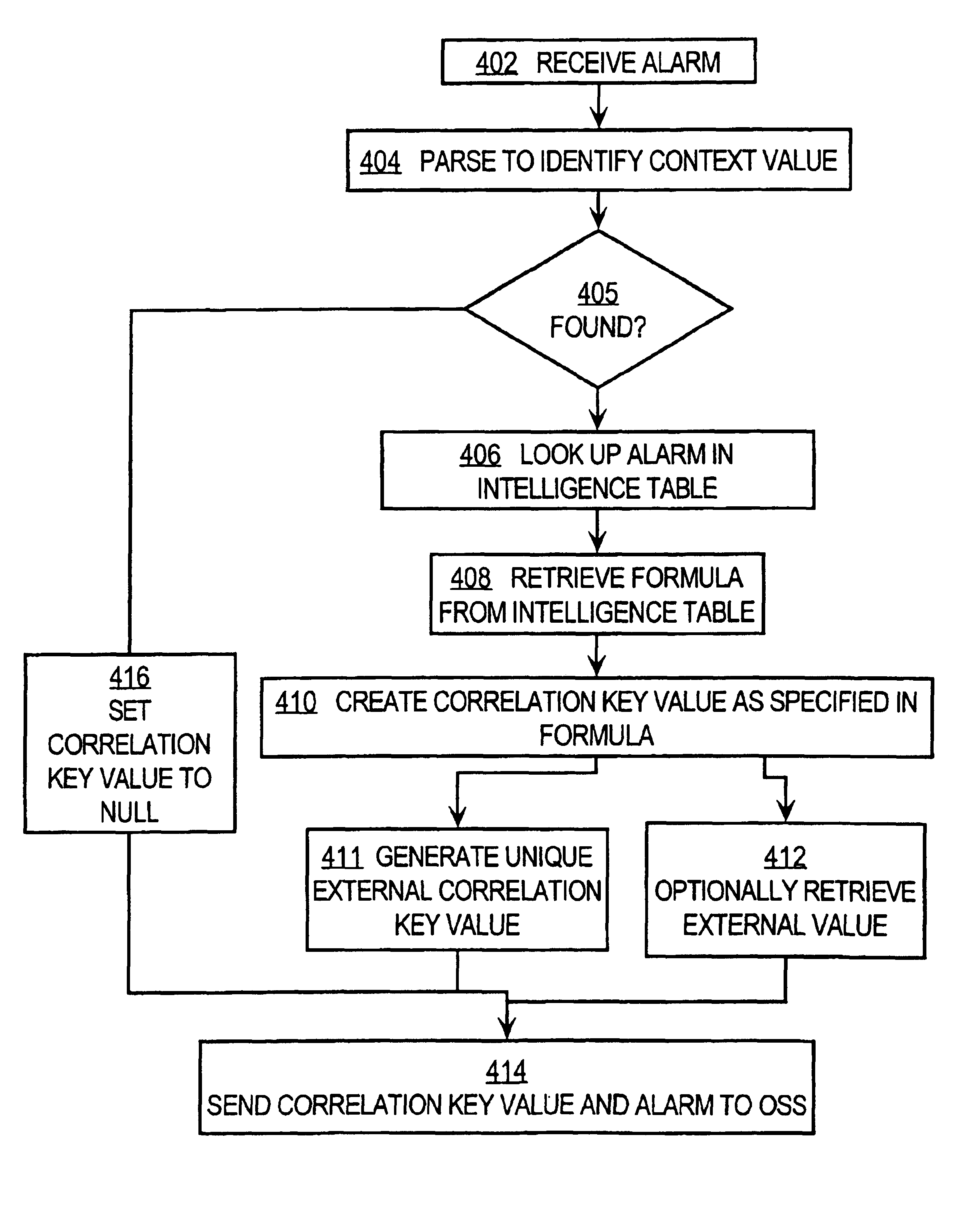
[0038]FIG. 4 is a flow diagram of a process of generating an alarm correlation value; and

[0039]FIG. 5 is a block diagram that illustrates a computer system upon which an embodiment may be implemented.

DETAILED DESCRIPTION OF THE PREFERRED EMBODIMENT

[0040]A method and apparatus for generating a correlation key value for use in correlating alarms emitted by network elements or system elements in a telecommunications...


PUM


Abstract

A method for generating compressed correlation key values for use in correlating alarms generated by network elements in a telecommunications network is disclosed. An alarm message generated by a network element is received. A context value in the alarm message is identified. A table that associates context values to correlation key value formulas is maintained. A formula specifying how to generate the correlation key value is retrieved from the table. Each formula may specify, for an associated context value, one or more ordinal positions of fields in the alarm message, a concatenation of which yields the correlation key value. The correlation key value is created based on the formula. A unique ordinal number is generated to represent the correlation key value, which acts as a context key. The alarm message and correlation key value are sent to an external system for use in correlating alarms.

Description

FIELD OF THE INVENTION[0002]The present invention generally relates to data processing in the field of network management for data networks. The invention relates more specifically to a method and apparatus for generating labels to facilitate correlating alarms in a telecommunications network as part of network management.BACKGROUND OF THE INVENTION[0003]The data networks that are deployed by service providers or large enterprises often comprise hundreds or thousands of network devices. A network device may comprise one or more network elements, which are entities like modules, ports, slots etc. The network devices and their corresponding network elements may be managed by one or more network management systems, such as an operational support system (OSS), which are implemented using computer application programs that can communicate with the network devices. OSS applications are either obtained from commercially available sources or developed internally by telecommunications servic...

Claims


Application Information

Patent Timeline
IPC IPC(8): H04L12/24G06F11/07
CPCG06F11/0709G06F11/0769H04L41/0631H04L41/0213G06F11/079
Inventor SHYU, JACKSON
Owner CISCO TECH INC
Why Eureka
Try Eureka