Air ventilation system for a watercraft

a technology for air ventilation and watercraft, which is applied in the field of small watercraft, can solve the problems of not being comfortable for the rider, not efficiently utilizing the limited space within the hull, and not taking into account the need for ease of assembly of the watercraft, so as to achieve the effect of improving the air ventilation system

Inactive Publication Date: 2005-03-08
POLARIS IND INC
View PDF16 Cites 14 Cited by
  • Summary
  • Abstract
  • Description
  • Claims
  • Application Information

AI Technical Summary

Benefits of technology

According to a first aspect of the invention, there is provided a watercraft having an improved air ventilation system. The watercraft includes a hull, a deck, a propulsion device and an engine. The hull is divided in half lengthwise by a centerline to create a first side and a second side. The deck is located on the hull and is divided in half lengthwise by the centerline. The propulsion device is carried by the hull for propelling the watercraft and the engine is positioned within the hull to drive the propulsion device. The

Problems solved by technology

On the other hand, because the rider's seat is defined above the engine compartment as noted above, the capacity and height of the engine compartment is limited.
Otherwise, the seat position must be higher and/or wider which may not be comfortable for the rider.
Existing watercraf

Method used


Image

  • Air ventilation system for a watercraft
  • Air ventilation system for a watercraft
  • Air ventilation system for a watercraft

Examples


Embodiment Construction

The following detailed description should be read with reference to the drawings, in which like elements in different drawings are numbered identically. The drawings depict selected embodiments and are not intended to limit the scope of the invention. It will be understood that embodiments shown in the drawings and described above are for illustrative purposes, and are not intended to limit the scope of the invention as defined in the claims that follow.

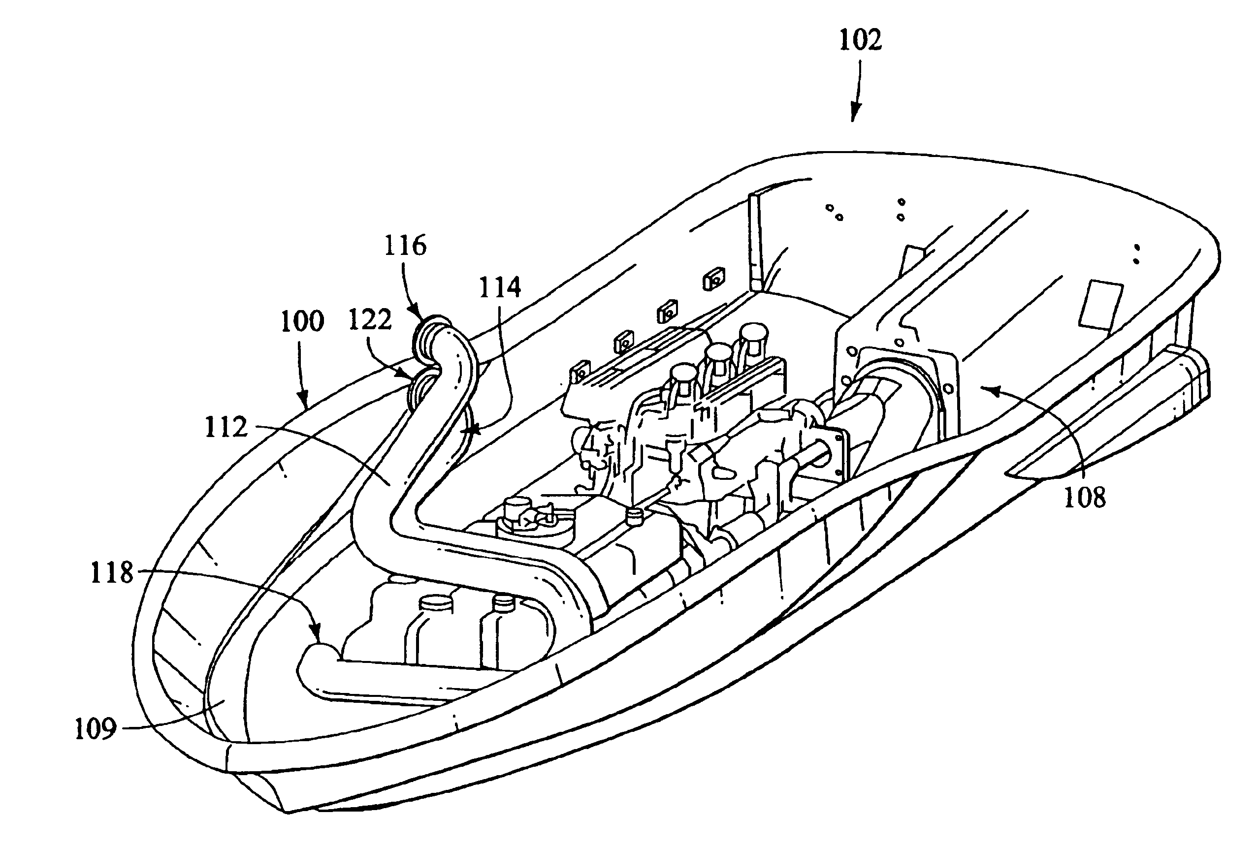
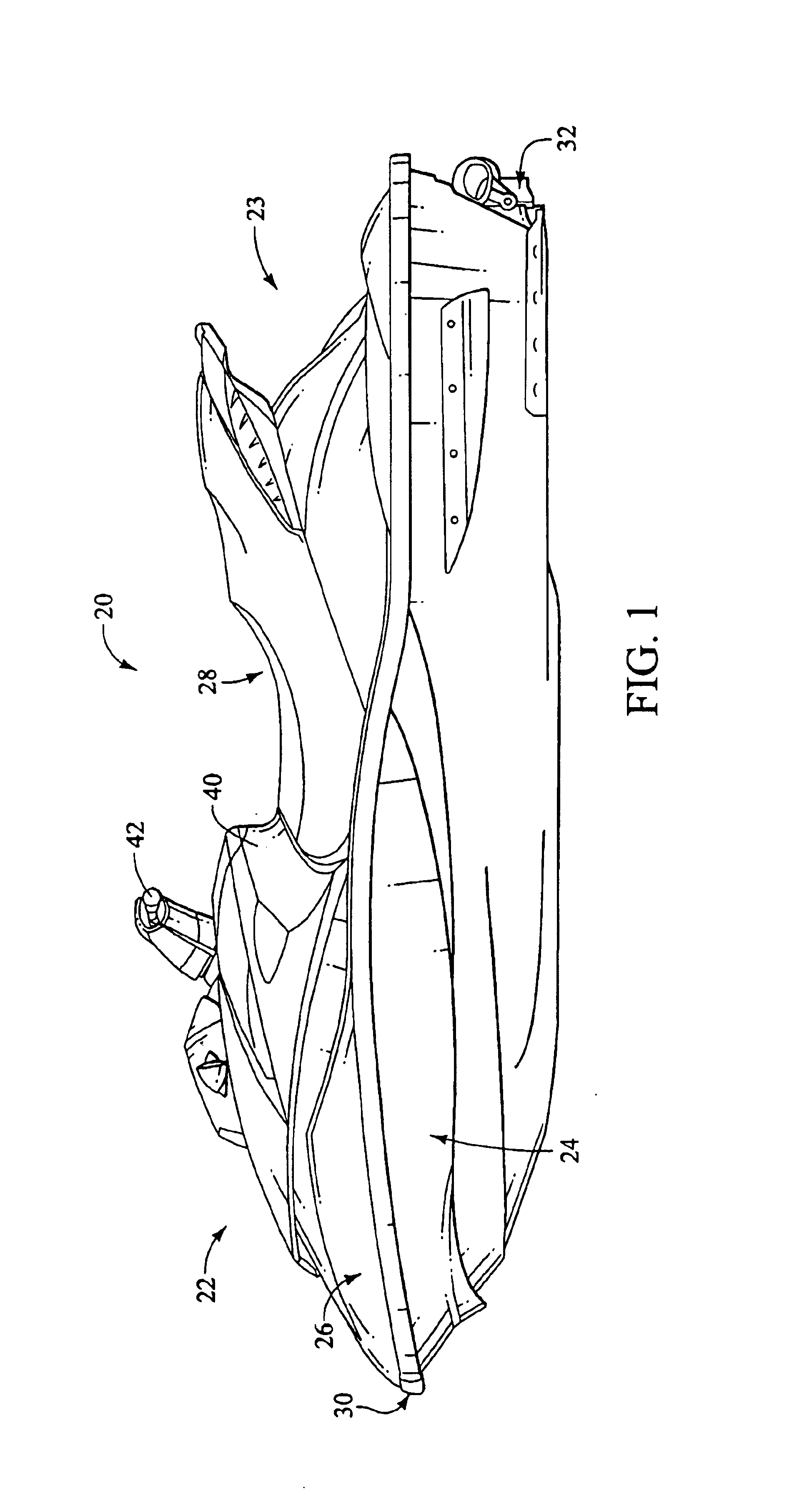
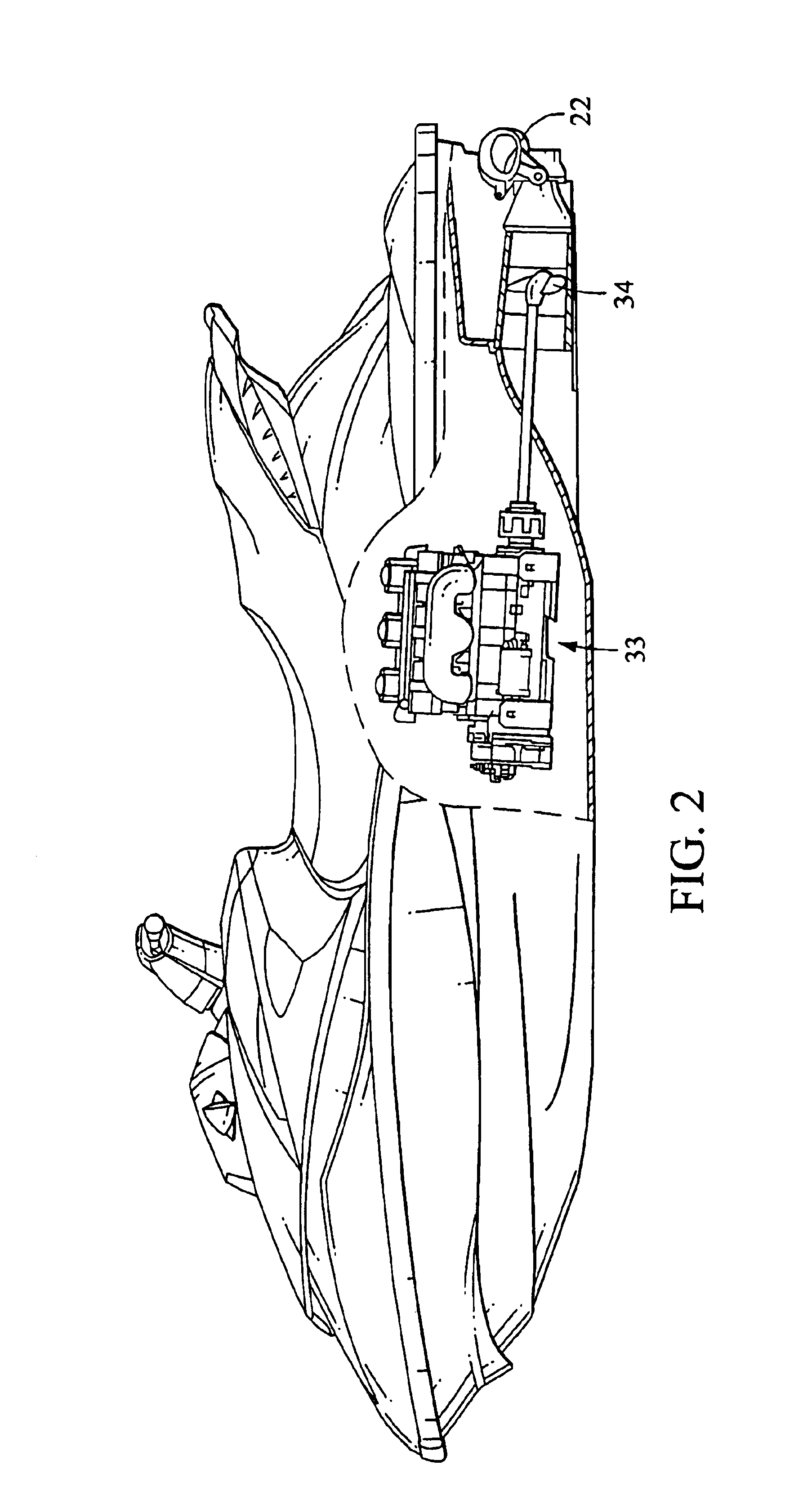
FIG. 1 is a perspective view of a personal watercraft according to a preferred embodiment of the present invention. The personal watercraft 20 includes generally a front or bow 22 and a rear or stem 23. The personal watercraft 20 includes a top deck 26 secured to a bottom hull 24 along an overlapping portion covered with a rub rail 30 in the embodiment illustrated, thereby forming a hull. The hull includes an exhaust opening (not shown). The hull formed by the bottom hull 24 and top deck 26 define a compartment sized to contain an in...


PUM


Abstract

An air ventilation system for a personal watercraft that includes a pair of pipes extending substantially side by side through the watercraft's hull from a first side to a second side where the pipes have an intake port located through the deck above the waterline of the watercraft and an outlet port that extends into the bottom third of the hull below the waterline.

Description

FIELD OF THE INVENTIONThis invention relates to small watercraft such as a personal watercraft and, more particularly, to an improved ventilation system therefore.BACKGROUND OF THE INVENTIONPersonal watercrafts are a popular type of watercraft in which one or more passengers ride on, rather than in, the watercraft.Frequently, these watercrafts are sporting in nature, and the riders expect to leave the watercraft at times during its use and enter into the body of water in which the watercraft is operating.A relatively small hull of a personal watercraft defines a rider's area above an engine compartment. An internal combustion engine powers a jet propulsion unit, which propels the watercraft. The engine lies within the engine compartment in front of a tunnel formed on an underside of the hull. The jet propulsion unit, which includes an impeller, is placed within the tunnel. The impeller has an impeller shaft driven by the engine. The impeller shaft usually extends between the engine ...

Claims


Application Information

Patent Timeline
IPC IPC(8): B63J2/00B63B35/73B63J2/06
CPCB63B35/731B63J2/06Y02T70/72B63B34/10Y02T70/00
Inventor WYNNE, DALLAS
Owner POLARIS IND INC
Why Eureka
Try Eureka