Method for reducing temperature rise of half-speed large-current collecting ring device

A collector ring, high current technology, used in electromechanical devices, cooling/ventilation devices, electrical components, etc., can solve the bottleneck of the surface working conditions of carbon brushes and slip rings, the cooling effect of centrifugal fans is reduced, and the power loss of collector rings increase, etc.

Active Publication Date: 2014-02-05
SHANGHAI ELECTRIC POWER GENERATION EQUIPMENT CO LTD
View PDF6 Cites 0 Cited by
  • Summary
  • Abstract
  • Description
  • Claims
  • Application Information

AI Technical Summary

Problems solved by technology

The speed of the four-pole generator is half that of the two-pole generator. Since the speed is halved, the cooling effect of the centrifugal fan is greatly reduced. At the same time, as the excitation current increases, the electrical loss

Method used


Image

  • Method for reducing temperature rise of half-speed large-current collecting ring device
  • Method for reducing temperature rise of half-speed large-current collecting ring device
  • Method for reducing temperature rise of half-speed large-current collecting ring device

Examples


Embodiment Construction

[0019] In order to make the present invention more obvious and understandable, the present invention will be further described with preferred embodiments.

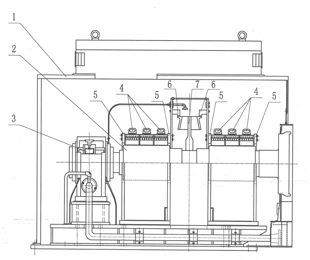
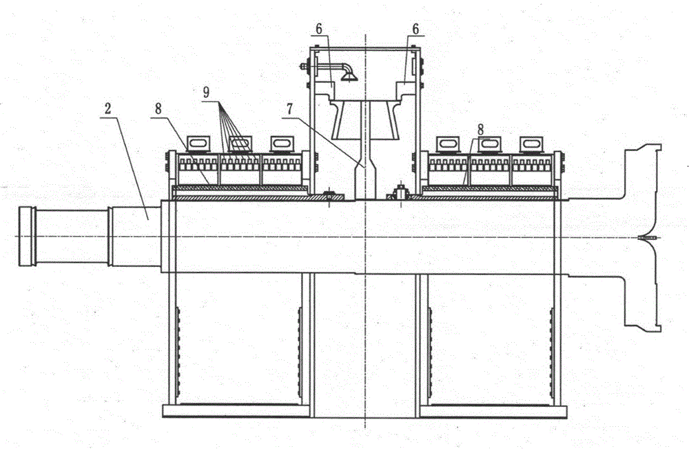
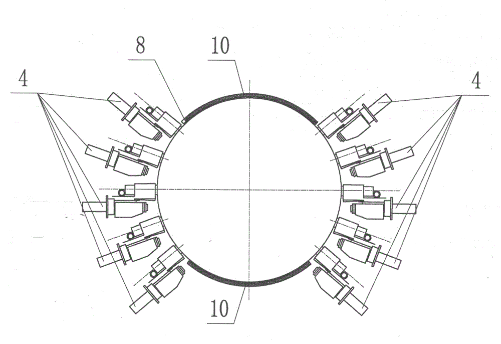
[0020] combine Figure 1 to Figure 3 , the invention provides a method for reducing the temperature rise of a half-speed high-current slip ring device, the steps of which are:

[0021] Step 1. Increase the diameter of the collector ring 2 to 450mm, increase the number of carbon brushes 9 to 360, optimize the arrangement of the carbon brushes 9 on the collector ring 2, reduce the current density of each carbon brush, and prevent local overheat. Each slip ring 8 assembled on the collector ring 2 is equipped with 3 rows in the axial direction, and each row has 10 combined brush holders 4 in the circumferential direction, and each combined brush holder 4 is equipped with 6 carbon brushes 9 .

[0022] Step 2. Increase the diameter of the centrifugal fan 7 located between a pair of slip rings 8 to 1200mm to make up for the los...


PUM

PropertyMeasurementUnit
Diameteraaaaaaaaaa
Diameteraaaaaaaaaa

Abstract

The invention provides a method for reducing the temperature rise of a half-speed large-current collecting ring device. The method for reducing the temperature rise of the half-speed large-current collecting ring device aims to improve the current-carrying capacity of the half-speed collecting ring device. The diameter of the collecting ring device is increased, the number of carbon brushes is increased, the arrangement of the carbon brushes on a collecting ring is optimized, meanwhile, the diameter of a centrifugal fan is increased, a ventilation system of the collecting ring device is optimized, and therefore the surface temperature of a sliding ring is lowered to be within a permitted range of not larger than 80K. The method effectively reduces the temperature rise of the half-speed large-current collecting ring device, and improves the current-carrying capacity of the collecting ring to the 10000A level.

Description

technical field [0001] The invention relates to a method for reducing the temperature rise of a half-speed high-current collector ring device, which belongs to the technical field of steam turbine generators. Background technique [0002] In a large turbogenerator, there are usually two ways to connect the excitation current to the generator, one is the coaxial brushless exciter method, and the other is the collector ring device method. The collector ring method uses the coupling between the static carbon brush on the brush holder and the rotating collector ring in the device to connect the excitation current to the generator. The collector ring device is favored by users for its simple structure, stable shafting and fast response. As the excitation current required by the generator increases, the current-carrying capacity of the collector ring device is required to be increased, and the temperature rise and cooling in the collector ring device have become a technical bottl...

Claims


Application Information

Patent Timeline
IPC IPC(8): H02K9/28
Inventor 干保良范成西何明艳朱天向顾守录史德利
Owner SHANGHAI ELECTRIC POWER GENERATION EQUIPMENT CO LTD
Why Eureka
Try Eureka