Wastewater aeration system with lift out lateral pipes and diffusers

a technology of lateral pipes and aeration systems, applied in the direction of carburettant air, filtration separation, separation processes, etc., can solve the problems of large machinery for removing solids, difficult to obtain clear access to the floor, and serious inhibition of the effectiveness of air diffusers

Inactive Publication Date: 2005-03-08
ENVIRONMENTAL DYNAMICS INC
View PDF9 Cites 18 Cited by
  • Summary
  • Abstract
  • Description
  • Claims
  • Application Information

AI Technical Summary

Benefits of technology

In addition to being pivoted upwardly along the basin wall, the laterals can be provided with a vertical track allowing the laterals and diffusers to be raised out of the water for maintenance. The basin floor can then be maintained without requiring de-watering of the basin.

Problems solved by technology

When the solids accumulation becomes excessive, it can seriously inhibit the effectiveness of the air diffusers.
However, because of all of the piping and diffusers located in the basin and extending along its floor, it is difficult to obtain clear access to the floor so that the solids can be removed.
The presence of the pipes and diffusers near the basin floor obstructs the floor area so that large machinery for removing the solids cannot be used in the basin.
As a result, the maintenance expense and the downtime of the treatment system are often substantial.

Method used


Image

  • Wastewater aeration system with lift out lateral pipes and diffusers
  • Wastewater aeration system with lift out lateral pipes and diffusers
  • Wastewater aeration system with lift out lateral pipes and diffusers

Examples


Embodiment Construction

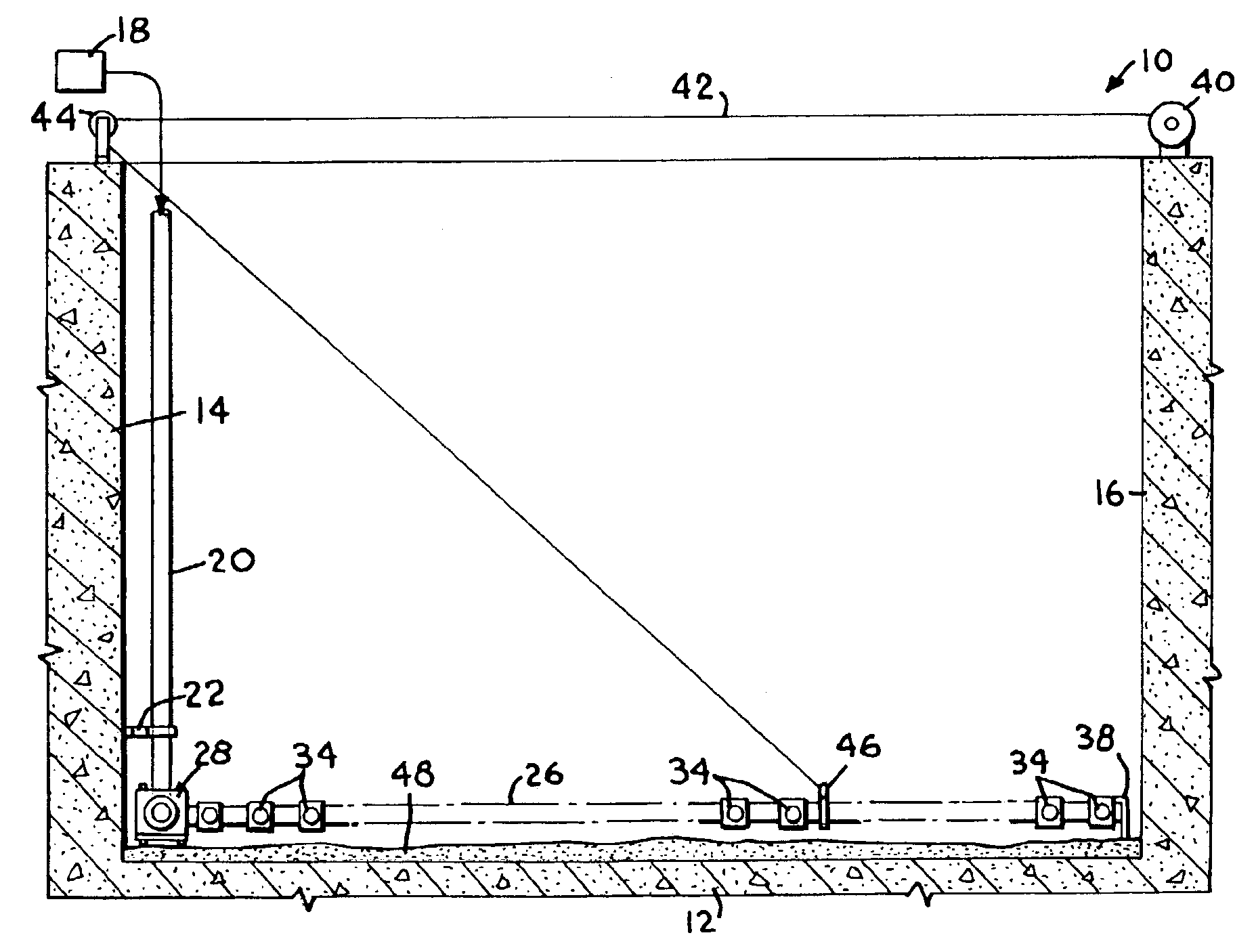
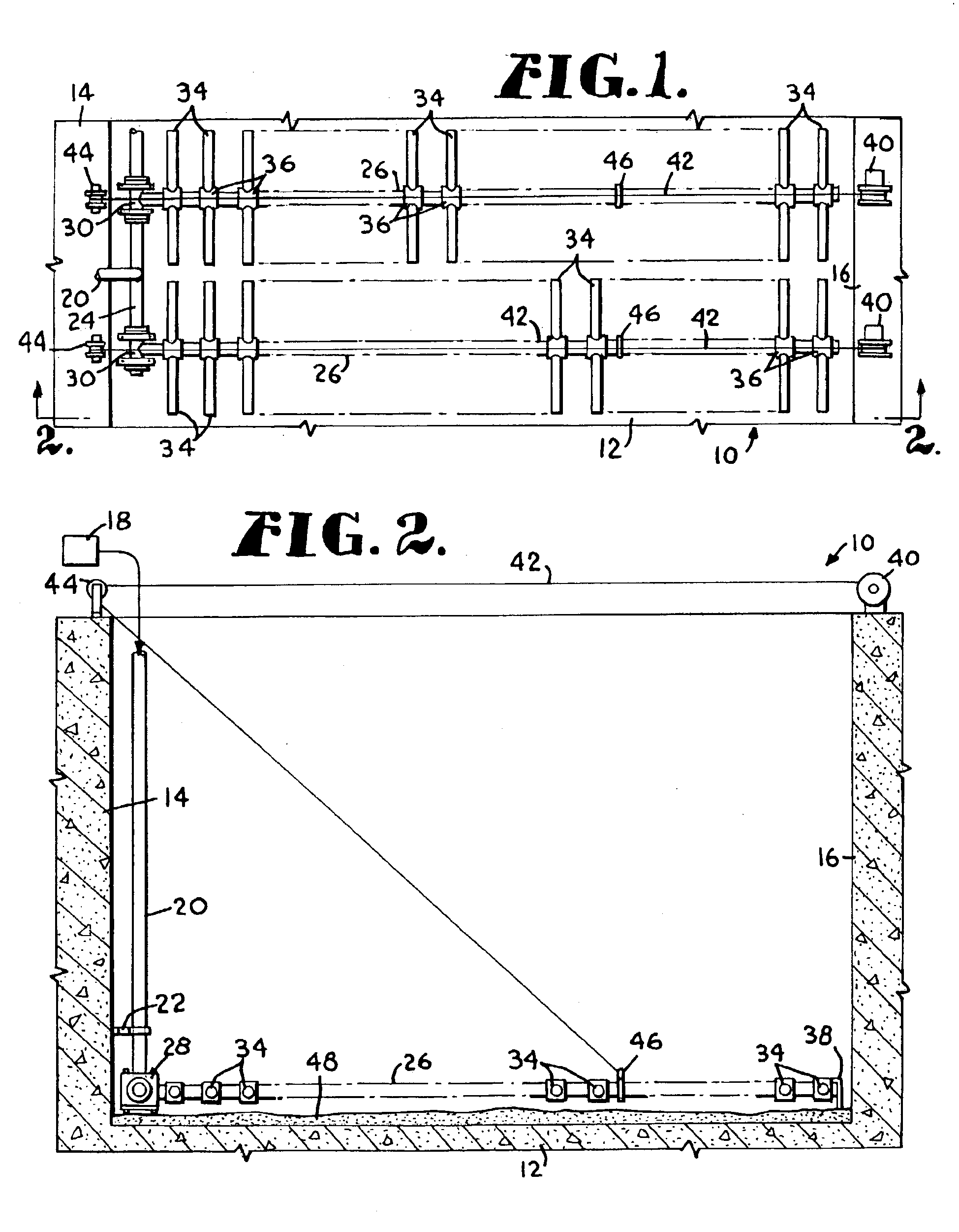
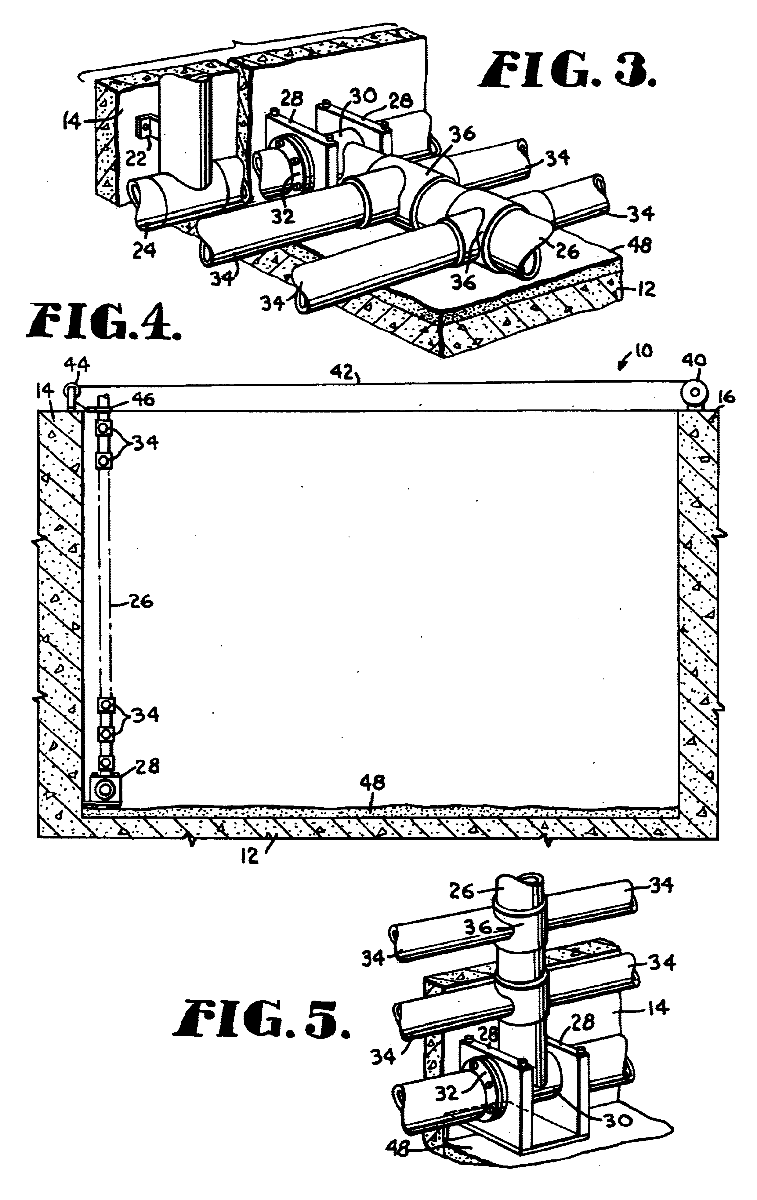
Referring now to the drawings in more detail, and initially to FIGS. 1-5, numeral 10 generally designates a basin that is used for the treatment of wastewater. The basin 10 may be constructed of concrete. As best shown in FIG. 2, the basin 10 has a generally horizontal floor 12 and opposite side walls 14 and 16. The basin 10 also includes opposite end walls in order to confine the wastewater that is aerated and mixed in the basin.

In accordance with the present invention, an aeration system for aerating and mixing the wastewater is provided. The preferred aeration system includes a blower 18 or other source of air that delivers air under pressure to one or more air supply pipes 20 that extend downwardly into the basin 10 along one of the walls such as wall 14. Suitable brackets 22 are used to anchor the air supply pipes 20 to the wall 14. The lower end of each supply pipe 20 connects with a header pipe 24 that extends horizontally generally along the floor 12 of the basin 10 adjacent...


PUM

PropertyMeasurementUnit
areaaaaaaaaaaa
depthaaaaaaaaaa
flexibleaaaaaaaaaa

Abstract

A wastewater aeration system that can be pivoted upwardly to expose the treatment basin floor for removal of accumulated grit or other solids. The aeration system includes a blower and a rigid or flexible supply conduit extending into the basin to supply lateral pipes with air. The laterals normally extend horizontally along the basin floor and carry air diffusers which discharge air into the basin. A winch and cable system or other mechanism can be operated to pivot the lateral pipes and diffusers upwardly away from the basin floor so that they are out of the way of equipment used to remove grit from the floor. A vertical track may be provided along a wall of the basin to accommodate raising of the lateral pipes and diffusers out of the basin.

Description

FIELD OF THE INVENTIONThis invention relates generally to the field of wastewater treatment and more particularly to an aeration system arranged to allow air supply laterals and diffusers carried on them to be pivotally raised from the treatment basin floor to allow full access to the basin floor for maintenance.BACKGROUND OF THE INVENTIONIn the treatment of wastewater, diffuser systems are used for aeration and mixing of the wastewater in a treatment basin. The diffuser system typically includes a blower which supplies air to one or more header pipes. In many systems, the header pipes connect with supply pipes which extend into the basin containing the wastewater. In treatment processes such as activated sludge systems making use of concrete basins, the supply pipes extend down to a location near the basin floor and connect with a lateral piping system. The lateral pipes reach into or across the basin, are anchored to the basin floor and may be equipped with air diffusers that disc...

Claims


Application Information

Patent Timeline
Patent Type & Authority Patents(United States)
IPC IPC(8): C02F3/20
CPCC02F3/205Y10S261/70Y10S261/47Y02W10/10
Inventor CHANN, RANDALL C.
Owner ENVIRONMENTAL DYNAMICS INC
Why Eureka
Try Eureka