
Modular diffuser body and aeration system

a technology of aeration system and diffuser body, which is applied in the direction of respirator, carburetor air, separation process, etc., can solve the problems of increasing complexity, cost and maintenance requirements, and reducing reliability, so as to achieve the effect of increasing the complexity of the diffuser body and reducing the cost and maintenance requirements

Inactive Publication Date: 2012-03-15
ENVIRONMENTAL DYNAMICS INC
View PDF6 Cites 24 Cited by
  • Summary
  • Abstract
  • Description
  • Claims
  • Application Information

AI Technical Summary

Problems solved by technology

Although the aforementioned diffuser systems function well for the most part, they are not wholly free of problems.
They each involve a large number of parts thereby increasing their complexity, cost and maintenance requirements and decreasing their reliability.
However, the aforementioned diffuser systems are often unable to achieve a high degree of efficiency primarily because, due to design and cost constraints, they are unable to achieve a relatively large area of perforated membrane as compared to the total surface area of the floor of the vessel in which they are installed.
An additional limitation for the size of the treatment vessel has been the length to which the diffuser system's lateral pipes could extend.
Securing a lateral pipe fixedly at both ends or along its length results in force on the pipe and the brackets or mounts holding the pipe in place as the pipe expands and contracts.
The pipe may bow and / or crack during the expansion and contraction.
Additionally, the brackets or mounts holding the pipe may become bent or broken under the force.

Method used


Image

  • Modular diffuser body and aeration system
  • Modular diffuser body and aeration system
  • Modular diffuser body and aeration system

Examples


Embodiment Construction

[0042]The invention will now be described with reference to the drawing figures, in which like reference numerals refer to like parts throughout. For purposes of clarity in illustrating the characteristics of the present invention, proportional relationships of the elements have not necessarily been maintained in the drawing figures.

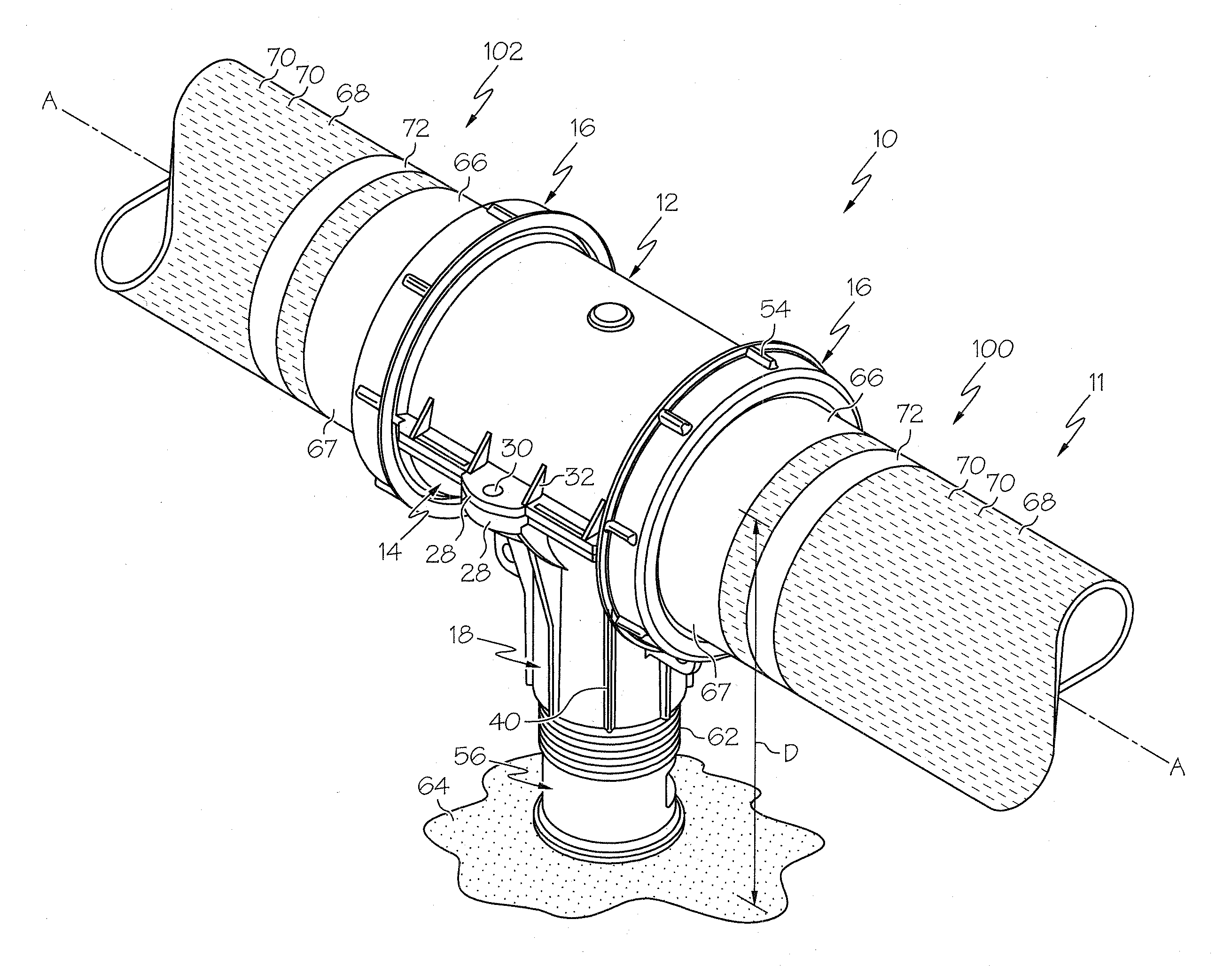
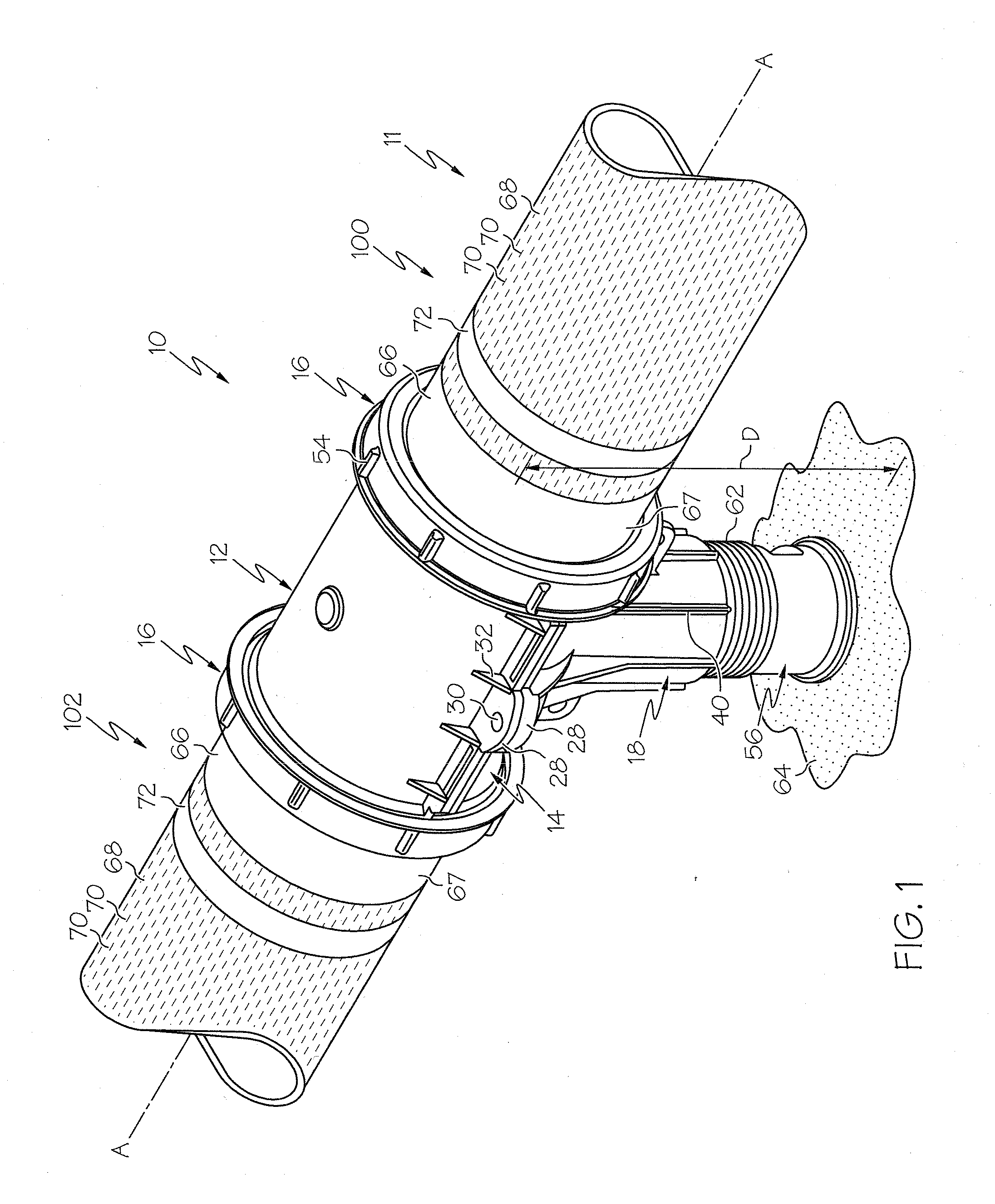
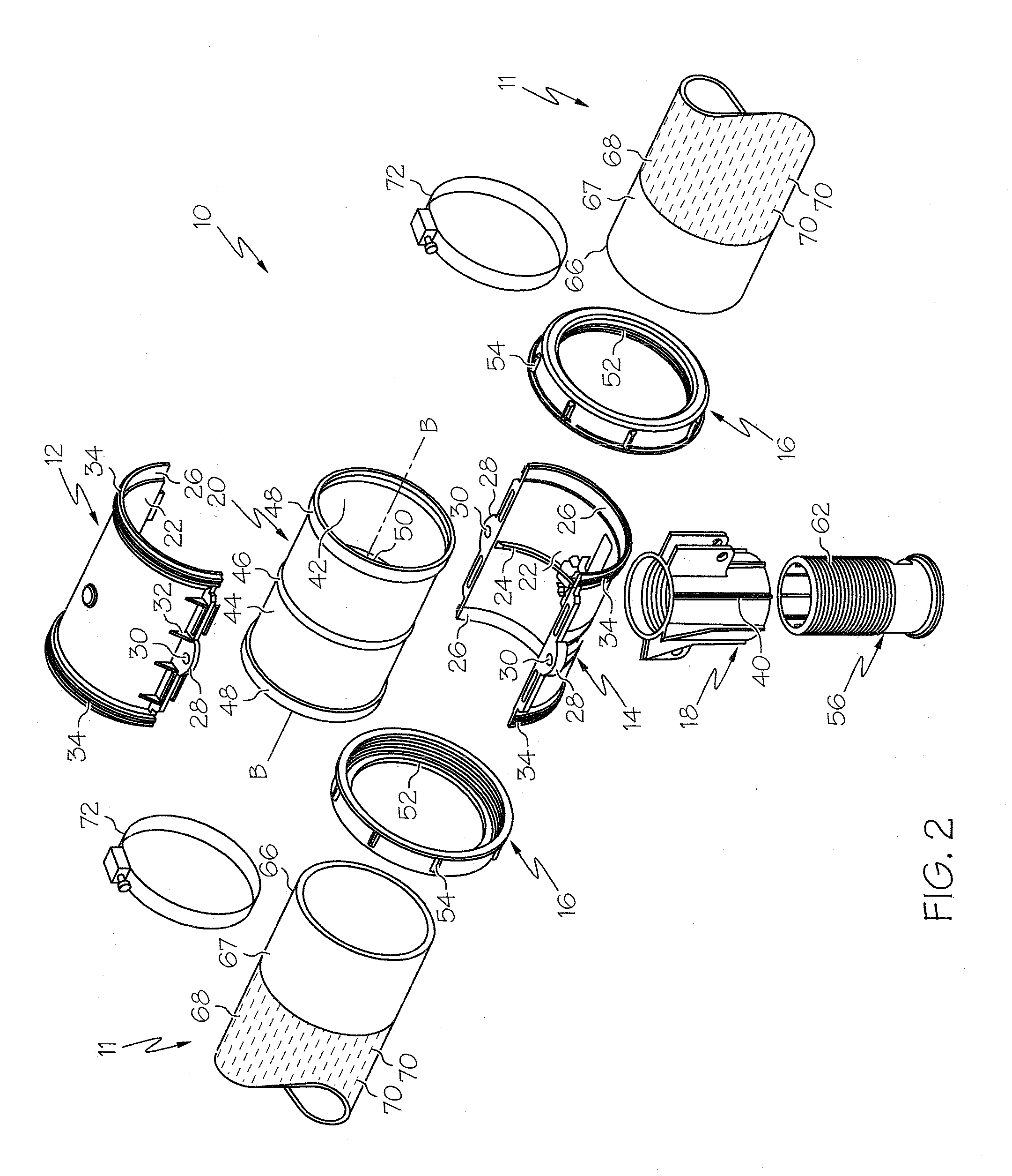
[0043]Referring to the FIG. 1, numeral 10 generally designates a coupling assembly for sealing joining the end portions of two adjacent lateral pipes 66 that extend horizontally generally along the bottom of a treatment vessel. The coupling assembly 10 may be of a split configuration and include first and second clamp members or saddle sections 12 and 14 that are sized and shaped to cooperate and extend around end portions of the pipes 66. While the saddle sections 12 and 14 are illustrated as having a generally semi-circular or arc-shaped cross-section, it will be understood that they may take other shapes, such as generally oval, triangular, rectangula...


PUM

PropertyMeasurementUnit
lengthaaaaaaaaaa
distanceaaaaaaaaaa
flexibleaaaaaaaaaa

Abstract

An aeration system for treating liquid contained in a vessel is provided. The aeration system includes a header pipe and a plurality of lateral pipes coupled to the header pipe. The lateral pipes each have one or more tubular diffuser membranes sleeved therearound. Also provided is a coupling for sealingly joining end portions of two adjacent pipes is provided. The coupling includes two saddle sections and a deformable gasket extending between the pipes. The coupling is adapted for enabling one pipe to be removed and replaced from a series of pipes without substantially moving any adjacent pipes.

Description

CROSS-REFERENCE TO RELATED APPLICATIONS[0001]This Application claims priority to U.S. Provisional Patent Application Ser. No. 61 / 381,900 filed Sep. 10, 2010 to Charles E. Tharp and Randall C. Chann entitled “Method and Apparatus for Aerating Wastewater,” currently pending, the entire disclosure of which is incorporated herein by reference. This Application also claims priority to U.S. Provisional Patent Application Ser. No. 61 / 382,745 filed Sep. 14, 2010 to Charles E. Tharp and Randall C Chann entitled “Method and Apparatus for Aerating Wastewater,” currently pending, the entire disclosure of which is incorporated herein by reference.BACKGROUND OF THE INVENTION[0002]In the aerobic biological treatment of wastewater and other liquids, it is common practice to provide an aeration system to oxygenate the liquid by dispersing pressurized air in a treatment vessel which contains the liquid. The aeration system is commonly comprised of an air distribution piping system including a main di...

Claims


Application Information

Patent Timeline
Patent Type & Authority Applications(United States)
IPC IPC(8): B01F3/04F16L21/06
CPCB01F3/04269B01F2003/04148F16L21/06B01F2003/04177B01F2003/04198B01F2003/0417B01F23/23113B01F23/231142B01F23/231152B01F23/231143B01F23/23124
Inventor THARP, CHARLES E.CHANN, RANDALL C.HULSEBUS, RANDY K.
Owner ENVIRONMENTAL DYNAMICS INC
Learn More