System and method for micro-aeration based fermentation

a technology of micro-aeration and fermentation, applied in specific use bioreactors/fermenters, gas production bioreactors, after-treatment of biomass, etc., can solve the problems of product yield loss, less tolerance of toxic concentration levels, and general less robust microorganisms

Inactive Publication Date: 2013-12-05
PRAXAIR TECH INC
View PDF3 Cites 26 Cited by
  • Summary
  • Abstract
  • Description
  • Claims
  • Application Information

AI Technical Summary

Benefits of technology

[0013]The present invention may be characterized as a micro-aeration based fermentation system comprising: (i) a fermentation reactor; (ii) a sparging apparatus disposed in the fermentation reactor; (iii) a micro-aeration gas mixture delivered to the fermentation reactor via the sparging apparatus, the micro-aeration gas mixture comprising an oxygen containing gas and an inert carrier gas; and (iv) an off-gas recycle loop configured to recycle off-gases exiting the fermentation reactor back to the sparger apparatus. The oxygen concentration in the micro-aeration gas mixture is less than or equal to 20%, and the micro-aeration gas mixture is delivered to the fermentation reactor at a minimum superficial velocity of 0.02 m / sec to mix the fermentation broth within the fermentation reactor and disperse the oxygen throughout the fermentation broth.

Problems solved by technology

However, such microbes are generally less robust during anaerobic conditions in the consumption of wide ranges of complex nutrients and less tolerant of toxic concentration levels of the products or byproducts being produced.
It is known, however, that these same microbes, under high oxygen tension, waste more nutrients during cell growth and may actually consume the desirable products that are being produced, thus resulting in product yield losses.
Practicing micro-aeration techniques in commercial scale or large scale fermenters with commercial success however, is very difficult.
Monitoring, controlling and dispersing the small amount of oxygen or air required in the fermenter are major issues in applying the micro-aeration technique to commercial scale or large scale fermentation operations.
However, sparging gas into a large fermenter without proper dispersing or bulk mixing causes some microbes to receive excess oxygen while others may be totally depleted of oxygen, even when the average oxygen uptake throughout the fermenter appears to be acceptable.
In order to measure DO levels during micro-aeration, the use of DO sensors or probes to measure and maintain the DO levels in the fermentation broth is common In practice, however, these laboratory conditions that produce the improved product yields cannot be easily duplicated or replicated in commercial or large scale fermenters.
As a result, many prior art fermentation systems are overly concerned with sparger configuration and location as well as the location and operation of mechanical agitators in the fermentation vessel or reactor.
Notwithstanding these efforts, in many commercial scale or large scale fermenters there remains certain spatial locations within the fermenter that are completely starved of oxygen and other areas where excessive oxygen is consumed.
However, such process is not suitable for many fermentation processes where excessive amounts of carbon dioxide have adverse effects on the process.
Because the carbon dioxide gas is introduced slowly into the fermentation broth and rapidly consumed as a nutrient in the Myriant process, the use of the Myriant micro-aeration process in large scale fermenters will still result in unbalanced DO levels throughout the fermeter with higher DO levels realized at locations proximate the spargers and lower DO levels realized at locations further away from the spargers.
This is primarily a result of the slow gas flow rates and rapid consumption of the carbon dioxide gas in the Myriant process which fails to provide proper dispersion or bulk mixing of the small amounts of oxygen throughout the fermentation broth.

Method used


Image

  • System and method for micro-aeration based fermentation
  • System and method for micro-aeration based fermentation
  • System and method for micro-aeration based fermentation

Examples


example

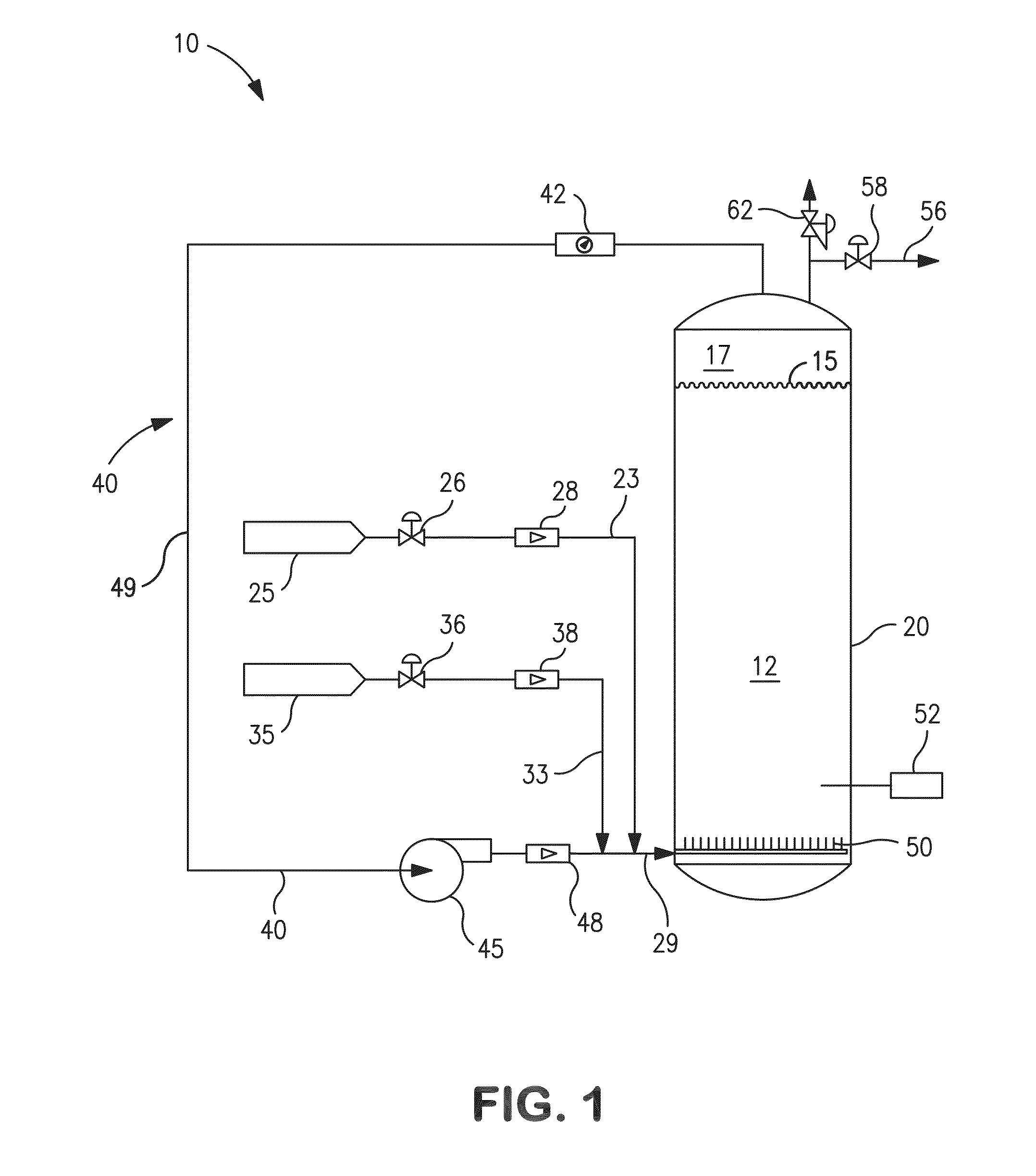
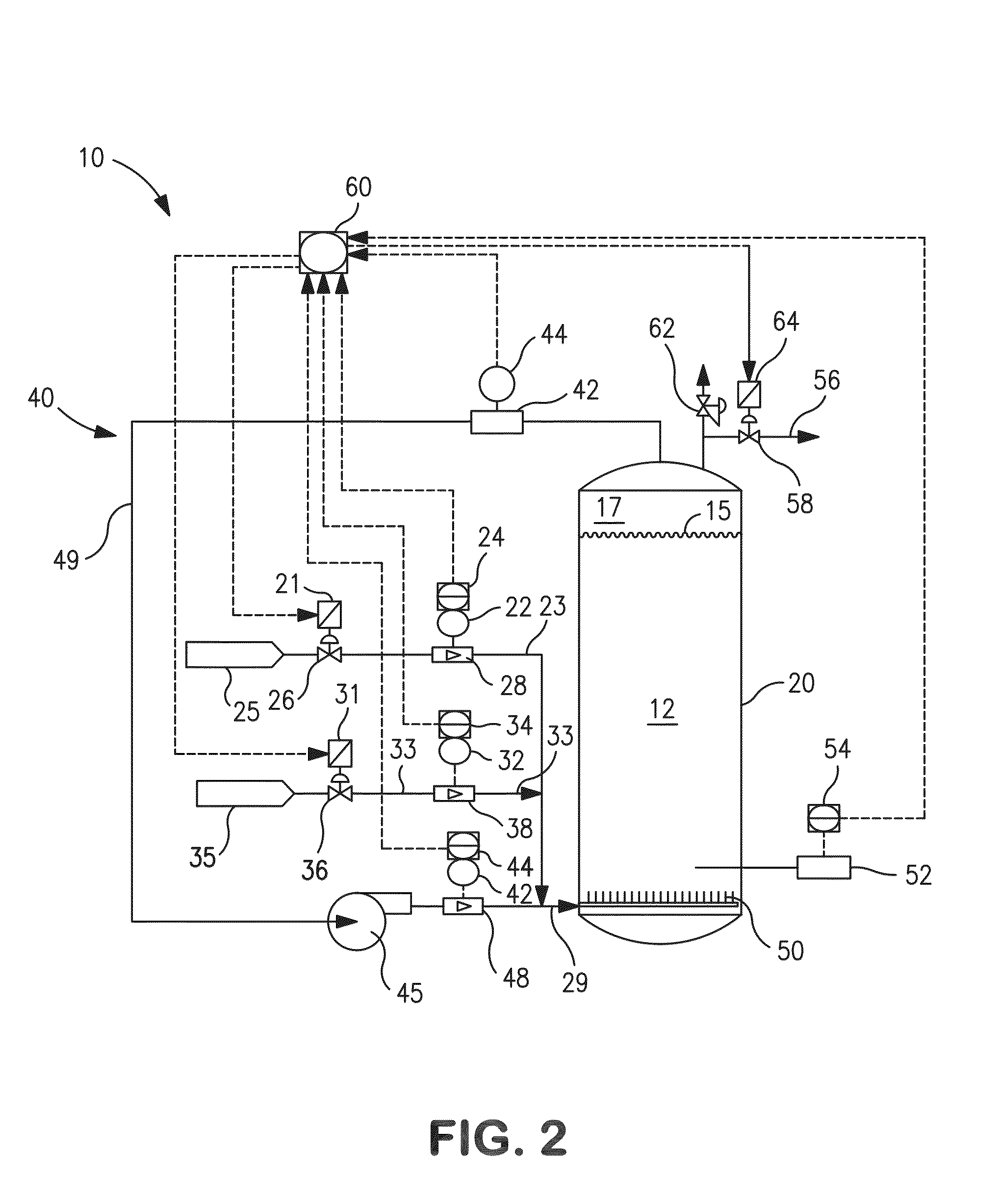
[0045]With reference to FIGS. 4A, 4B, 4C, and 4D, the following example shows the benefit of using respiratory quotient (RQ) as the preferred control parameter for micro-aeration based fermentation. As discussed above, RQ is defined as the molar ratio of the carbon dioxide evolution rate (CER) to the oxygen uptake rate (OUR). The OUR and CER were determined by measuring the gas flow rates and the concentrations of carbon dioxide and oxygen in the recycled off-gas. Under pseudo-steady-state and oxygen-limited conditions, the OTR can be calculated from the OUR. The comparison of 2, 3-BDO fermentation with RQ control and without RQ control was conducted using a 5 L fermenter employing the micro-aeration scheme as generally illustrated in FIG. 2. The control of OUR and RQ was realized by adjusting the aeration rate of the flow to the sparger.

[0046]When control of the micro-aeration based fermentation process is based simply on OUR (i.e. without RQ control), the maximum BDO yield (g / g) f...


PUM

PropertyMeasurementUnit
superficial velocityaaaaaaaaaa
volumeaaaaaaaaaa
superficial velocityaaaaaaaaaa

Abstract

A method and apparatus for micro-aeration of large scale fermentation systems is provided. The micro-aeration system includes a fermentation reactor, a sparging apparatus, and a micro-aeration gas mixture delivered to the fermentation reactor via the sparging apparatus. The micro-aeration gas mixture is a very low oxygen concentration mixture comprising an oxygen containing gas and an inert carrier gas that is preferably recycled through the fermentation reactor. The inert carrier gas is preferably nitrogen whereas the oxygen containing gas is oxygen or and is introduced to the fermentation reactor at a minimum superficial velocity of about 0.02 m/sec to produce a uniform dispersion of the oxygen/air throughout the fermentation broth while concurrently mixing the entire fermentation broth. The micro-aeration method and apparatus further comprises a controller operatively coupled to one or more control valves for regulating the micro-aeration conditions in the fermentation reactor.

Description

CROSS REFERENCE TO RELATED APPLICATIONS[0001]This application claims priority to and the benefit of U.S. provisional patent application Ser. No. 61 / 655,117 filed on Jun. 4, 2012, the disclosure of which is incorporated by reference herein.FIELD OF THE INVENTION[0002]The present invention broadly relates to fermentation processes, and more particularly, to devices, methods, and systems for providing, via micro-aeration, a controlled rate and concentration of highly diluted air or oxygen into and through a fermenter using an inert carrier gas, preferably nitrogen. By controlling the bulk flow rate and concentration of gas flows into the fermenter, the build-up and concentration of carbon dioxide can also be properly controlled. The primary purpose of providing these systems is for optimization of yields of biologically derived fermentation of microbes that in turn produce desirable chemical commodities such as alcohols and organic acids on a large industrial scale. The ability to use ...

Claims


Application Information

Patent Timeline
Patent Type & Authority Applications(United States)
IPC IPC(8): C12M1/00
CPCC12M29/24C12M27/00C12M29/06C12M41/32C12M41/34C12M21/12C12M41/48
Inventor CHENG, ALAN T.ZHOU, YINGBELANGER, PAUL W.BUGAYONG, JENNIFER G.
Owner PRAXAIR TECH INC
Why Eureka
Try Eureka