Locking device

a technology of locking device and control rod, which is applied in the direction of contact mechanism, switchgear with a retractable carriage, contact, etc., can solve the problem of restricted mobility of the first strip interacting with the control rod, and achieve the effect of extreme economic space us

Inactive Publication Date: 2005-03-08
SIEMENS AG
View PDF15 Cites 12 Cited by
  • Summary
  • Abstract
  • Description
  • Claims
  • Application Information

AI Technical Summary

Benefits of technology

The connection of the thrust element to the moveable first strip in itself creates the capability to prevent a tool being fitted to operate the drive spindle of a spindle drive The use of a control contour with a ramp allows the electrical switch to interact with the first strip in a simple manner via the moveable control rod. Thus, for example, the control rod can project rigidly into the control contour and block the first strip or, in the case of a control rod which can be moved if required, can also be moved along its longitudinal axis. The ramp can then be used in a particular manner to raise the control rod during movement of the first strip. However, if the control rod projects rigidly into the control contour (for example when the switch is connected), then the mobility of the first strip interacting with the control rod is restricted. The control contour of the first strip can be designed such that it has a number of ramps, for example in order to interact with a number of control rods. Furthermore, a number of ramps may be provided which alternately interact with one and the same control rod as a function of whether the switch is in the disconnected position or in the operating position. In addition to the blocking effect of the control rod by means of the control contour of the first strip, it is also possible for the first strip to act on the electrical switch by means of the control contour. It is thus possible, for example, to provide for switching of the switch to be blocked when the control rod is raised to a higher level by the ramp. Furthermore, it is possible to provide for forced disconnection of the electrical switch by a movement of the control rod by means of the control contour of the first strip, in order to ensure that the electrical switch is disconnected when it moves.
An arrangement such as this results in an arrangement of the individual locking conditions which is extremely economical in its use of space. This makes it possible to use the respectively available spatial conditions in an optimum manner. The individual assemblies can be arranged very close to one another.

Problems solved by technology

However, if the control rod projects rigidly into the control contour (for example when the switch is connected), then the mobility of the first strip interacting with the control rod is restricted.

Method used


Image

  • Locking device
  • Locking device
  • Locking device

Examples


Embodiment Construction

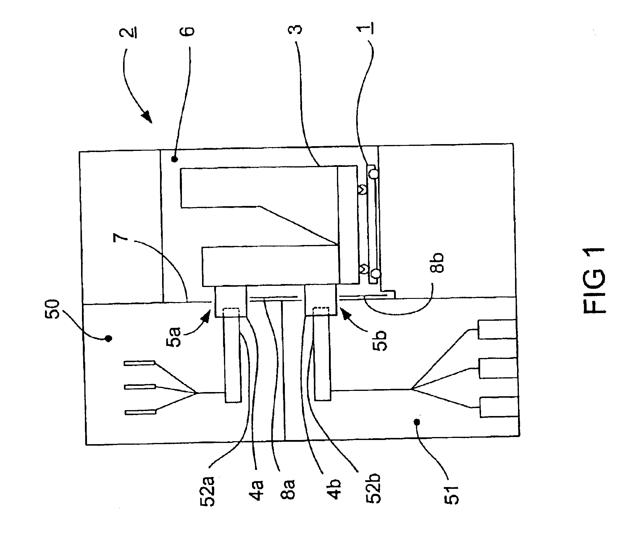
The mounting rack 1, as well as the components associated with it, can be inserted into and withdrawn from a switch area 6 of an encapsulated switch panel 2 (FIG. 1). This insertion and withdrawal are required essentially for maintenance purposes and for replacement of a defective mounting rack 1 or of assemblies arranged on the mounting rack 1. An electrical switch 3 can be moved relative to the mounting rack 1, between an operating position, a test position and a disconnected position. The connecting pieces 4a,b of the electrical switch 3 can be moved through openings 5a,b in a partition wall 7 of the switch panel 2. These openings 5a,b are closed by shutters 8a,b when the electrical switch 3 is in the test position or in the disconnected position. The partition wall 7 is adjacent to the switch area 6 on one side. A busbar area 50 and a cable connecting area 51 are located on the other side of the partition wall 7. The cable connecting area 51 and the busbar area 50 each include m...


PUM


Abstract

A locking device of an electrical switch which can be moved between a disconnected position and an operating position with the switching states of the electrical switch. A first strip has a control contour which extends in a first direction and has a ramp which interacts with a control rod which can be moved in certain states of the electrical switch.

Description

CLAIM FOR PRIORITYThis application claims priority to Application No. 10153107.9 which was filed in the German language on Oct. 22, 2001TECHNICAL FIELD OF THE INVENTIONThe invention relates to a locking device, and in particular, to a locking device for an electrical switch which can be moved relative to a mounting rack between a disconnected position and an operating position.BACKGROUND OF THE INVENTIONA locking device, by way of example, for switch panels is known from Section “8.2.4 Metallgekapselte luftisolierte Schaltfelder nach DIN EN 60298 (VDE 0670, Teil 6) [Metal encapsulated, air-insulated switch panels in accordance with DIN EN 60298 (VDE 0670, Part 6]” of the “ABB-Taschenbuch Schaltanlagen [ABB Manual on Switchgear Assemblies]”, 10th Edition, Cornelsen Verlag Berlin, [page 392. This describes a metal-compartmentalized switch panel, which is subdivided into a number of area elements, such as a busbar area, a cable connecting area and a switch area. An electrical switch is...

Claims


Application Information

Patent Timeline
Patent Type & Authority Patents(United States)
IPC IPC(8): H02B11/00H02B11/127
CPCH02B11/127
Inventor ANGER, NILSBIENER, MATTHIASRAUTMANN, STEFANRUDOLPH, DIETRICHSCHWARTZ, JAYSTELZER, ANDREAS
Owner SIEMENS AG
Why Eureka
Try Eureka