Method of building and updating an anisotropic velocity model for depth imaging of seismic data

an anisotropic velocity and depth imaging technology, applied in the direction of 2d-image generation, static indicating devices, instruments, etc., can solve the problems of not easily determinable parameter csub>13 /sub> by measurements parallel to and perpendicular to the symmetry axis, and gretchka & tsvankin do not address the interaction between

Inactive Publication Date: 2005-03-08
CONOCOPHILLIPS CO
View PDF7 Cites 50 Cited by
  • Summary
  • Abstract
  • Description
  • Claims
  • Application Information

AI Technical Summary

Benefits of technology

The present invention is a method of seismic prospecting over a region of interest having velocity anisotropy. Conventionally migrated seismic data are obtained using an isotropic velocity model wherein short offsets within a common image point gather have substantially flat moveouts. A model of vertical interval velocity as a function of depth is obtained using checkshots, VSPs, sonic logs, or geologic information. An initial model of an effective anellipticity parameter as a function of depth over the region of interest is obtained. Using the conventionally migrated seismic data, the model of vertical interval velocity as a function of depth and the anellipticity parameter as a function of depth, an anisotropic migrated image of the subsurface is obtained. By reviewing long offsets within common image points of the anisotropic migrated image, a residual anellipticity parameter is determined, the subsurface model is updated, and the migration is repeated. The anisotropic migrated image is preferably obtained using Kirchoff migration. The conventionally migrated seismic data may be obtained by Kirchoff migration, finite difference, or frequency domain methods.
Determination of the effective anellipticity parameter further comprises using semblance processing with non-hyperbolic moveout.
The Kirchoff migration is preferably carried out after a depth-to-time conversion of the effective anellipticity model. That is, following a layer stripping, models of the horizontal interval velocity and the anellipticity parameter are obtained as a function of time: this is followed by a conversion back to depth prior to the anisotropic imaging.

Problems solved by technology

In addition, shales exhibit transverse isotropy in their elastic properties even at very short seismic wavelengths.
However, the parameter c13 is not readily determinable by measurements parallel to and perpendicular to the symmetry axis.
Gretchka & Tsvankin do not address the interaction between iterative changes in the velocity model and subsequent changes in the accuracy of the depth image.

Method used


Image

  • Method of building and updating an anisotropic velocity model for depth imaging of seismic data
  • Method of building and updating an anisotropic velocity model for depth imaging of seismic data
  • Method of building and updating an anisotropic velocity model for depth imaging of seismic data

Examples


Embodiment Construction

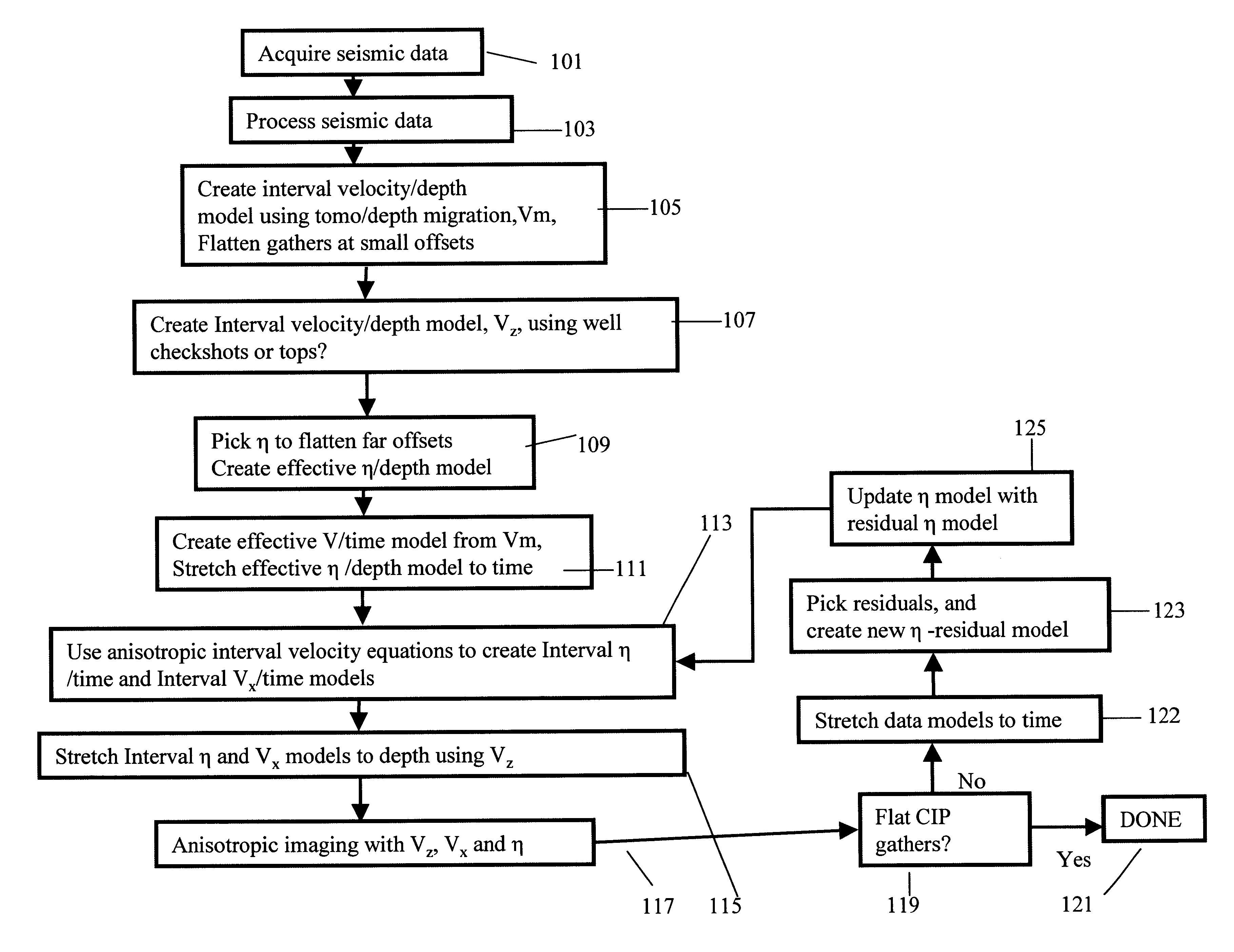
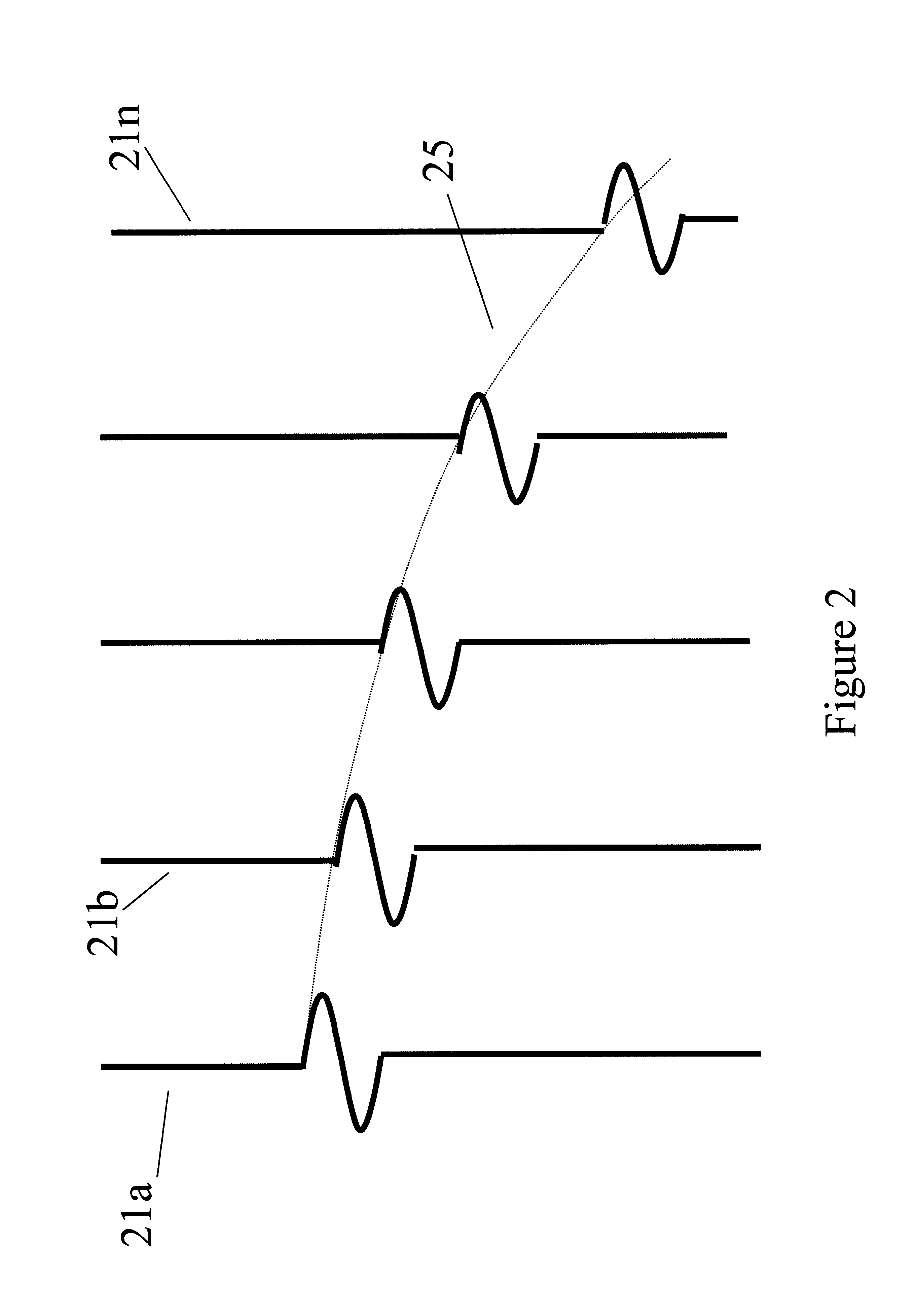
Turning now to FIG. 3, a flow chart that includes the preferred embodiment of the present invention is shown. Anisotropic depth migration requires three independent models: a vertical velocity model Vz, a horizontal velocity model Vx, and an anisotropy parameter model η satisfy this requirement. Seismic data over the region of interest are acquired or obtained 101 using any one of numerous well-known seismic exploration techniques. This gives seismic traces such as those depicted in FIG. 2 wherein one or more seismic reflections (or diffractions) appear on a plurality of seismic traces. Each seismic trace is associated with a source position and a receiver position. Shown in FIG. 4 is an example of a seismic section. It is to be noted that in actual practice, color displays are used for displays of seismic sections and diagnostics: this greatly increases the ease with which desired features can be seen. Black and white displays, as shown in this document, are usually adequate, but c...


PUM


Abstract

Conventional migration of short offset seismic data is performed. An interval velocity is obtained using, for example, check shots. An initial model of effective anellipticity parameter as a function of depth is obtained by flattening long offsets within a common image point. From these, interval anellipticity and horizontal velocity are obtained as a function of time. These initial models are used for anisotropic imaging. Any remaining residuals are used to update the interval anellipticity model and the process of migration is repeated until satisfactory results are obtained.

Description

BACKGROUND OF THE INVENTION1. Field of the InventionThe present invention is a method of obtaining an anisotropic velocity model for proper depth imaging of seismic data.2. Related Prior ArtThe search for subsurface hydrocarbon deposits typically involves a multifaceted sequence of data acquisition, analysis, and interpretation procedures. The data acquisition phase involves use of an energy source to generate signals which propagate into the earth and reflect from various subsurface geologic structures. The reflected signals are recorded by a multitude of receivers on or near the surface of the earth, or in an overlying body of water. The received signals, which are often referred to as seismic traces, consist of amplitudes of acoustic energy which vary as a function of time, receiver position, and source position and, most importantly, vary as a function of the physical properties of the structures from which the signals reflect. The data analyst uses these traces along with a geo...

Claims


Application Information

Patent Timeline
Patent Type & Authority Patents(United States)
IPC IPC(8): G06T11/20G09G5/00G01V1/30
CPCG01V1/303
Inventor MEEK, ROBERT A.ANNO, PHIL D.
Owner CONOCOPHILLIPS CO
Why Eureka
Try Eureka