Video transmission system and method utilizing phone lines in multiple unit dwellings

a video transmission system and phone line technology, applied in the field of video distribution systems, can solve the problems of affecting the attractiveness of the network in the same structure, the difficulty of distributing alternative source signals over proprietary cables, and the laborious cost of wiring a building for cabl

Inactive Publication Date: 2005-03-08
AUDIOVOX ELECTRONICS
View PDF46 Cites 124 Cited by
  • Summary
  • Abstract
  • Description
  • Claims
  • Application Information

AI Technical Summary

Benefits of technology

In a more complex embodiment of the present invention, at least two frequency bands would be utilized on each telephone wiring pair for the transmission of at least two channels of video, in accordance with minimum consumer expectations. The less complicated single band system might still find application in institutional settings, for example, hospitals, where no provision need be made for simultaneous recording of video programming. In a multiple band application, the terminal unit would differ in appearance from a normal cable box by the necessary indication of two selected channels, rather than one. Ordinarily additional unscrambled channels may be tuned by ‘cable ready’ VCR's and TV's from the broadband signal present on the cable. In the present system, since the broadband signal is not available at the individual units or terminal locations, the selection process involving command transmission to the rack mounted selector unit must operate for both, or all, selected channels. The selected channels could be provided at the terminal unit on two VHF channels unused by local broadcasting. Alternatively, or additionally, one channel could be provided on baseband ports suitable for direct connection to the typically unused baseband ports of a VCR. As pointed out by Goodman, numerous advantages accrue by using this mostly ignored capacity of VCR's, and, if the other selected channel is provided to the RF port of a VCR, the ability to watch one channel while recording another is gained by use of the “TV / VCR” switch present on almost all VCR's.
In an alternative embodiment of this invention, instead of concentration at a single central location, rack mounted selector units may be provided in an equipment closet located on each floor of a multiple floor structure. Coaxial cable may then be run in a single vertical riser, and interconnected with the phone lines branching off on each floor. Although some new cable must be run in this case, this has the advantage of limiting additional cable to a single unobtrusive location, without the necessity of entering each dwelling or commercial unit. The equipment closet should of course contain the rising bundle of telephone wires, so that pairs branching off on each floor may be conveniently broken into and a selector unit installed; i.e., wired in series.

Problems solved by technology

Wiring a building for cable entails a considerable labor expense, and, depending on the care of the installers, a more or less intrusive presence of cables or molding in public hallways, and in some cases, even dangling from the outsides of buildings.
Even when such an installation is already in place, regulations generally leave the cable installer, typically the local cable franchise, in monopoly possession of rights to use the local area network.
Although this situation may change in the future, in parallel with current trends in electrical distribution and phone networks, at present landlords or cooperative tenants face serious legal difficulties attempting to distribute alternative source signals over proprietary cables.
Circumventing this problem by installing a second independent cable distribution network in the same structure is clearly a less than appealing solution.
No attempts are known to the inventor to use plumbing as a transmission medium, which plan would clearly present formidable difficulties.
Appliances, however, are known to inject broadband RF energy into power lines, defeating efforts to utilize empty bandwidth above 50 Hz or 60 Hz alternating current.
Telephone wires entail their own technical and regulatory problems as a medium for the transmission of video signals.
Regulation imposes more stringent spectral requirements, however, limiting the amount of RF energy below 6 MHZ that may be injected into the public telephone network.
Further problems arise from the fact that telephone wiring was not designed for radio frequency transmission.
Telephone wiring lacks grounded shielding, which gives rise to further technical and legal problems.
On the transmission side, this means the wires carrying RF signals radiate significant electromagnetic energy, resulting in signal attenuation.
Boosting the signal will increase the maximum useful length of RF signal transmission on the wire, but simultaneously increase broadcast power and possibly cause interference to other devices, or run afoul of FCC radiation limits.
Conversely, on the reception side, lack of shielding makes the system vulnerable to outside sources of interference.
In general the problem of non-design utilization of unused transmission capacity in local area phone networks is one of choosing a power transmission spectrum extremizing an objective function weighted by both total information throughput and cost, and subject to technical and regulatory constraints on unintended interference with other devices.

Method used


Image

  • Video transmission system and method utilizing phone lines in multiple unit dwellings
  • Video transmission system and method utilizing phone lines in multiple unit dwellings
  • Video transmission system and method utilizing phone lines in multiple unit dwellings

Examples


Embodiment Construction

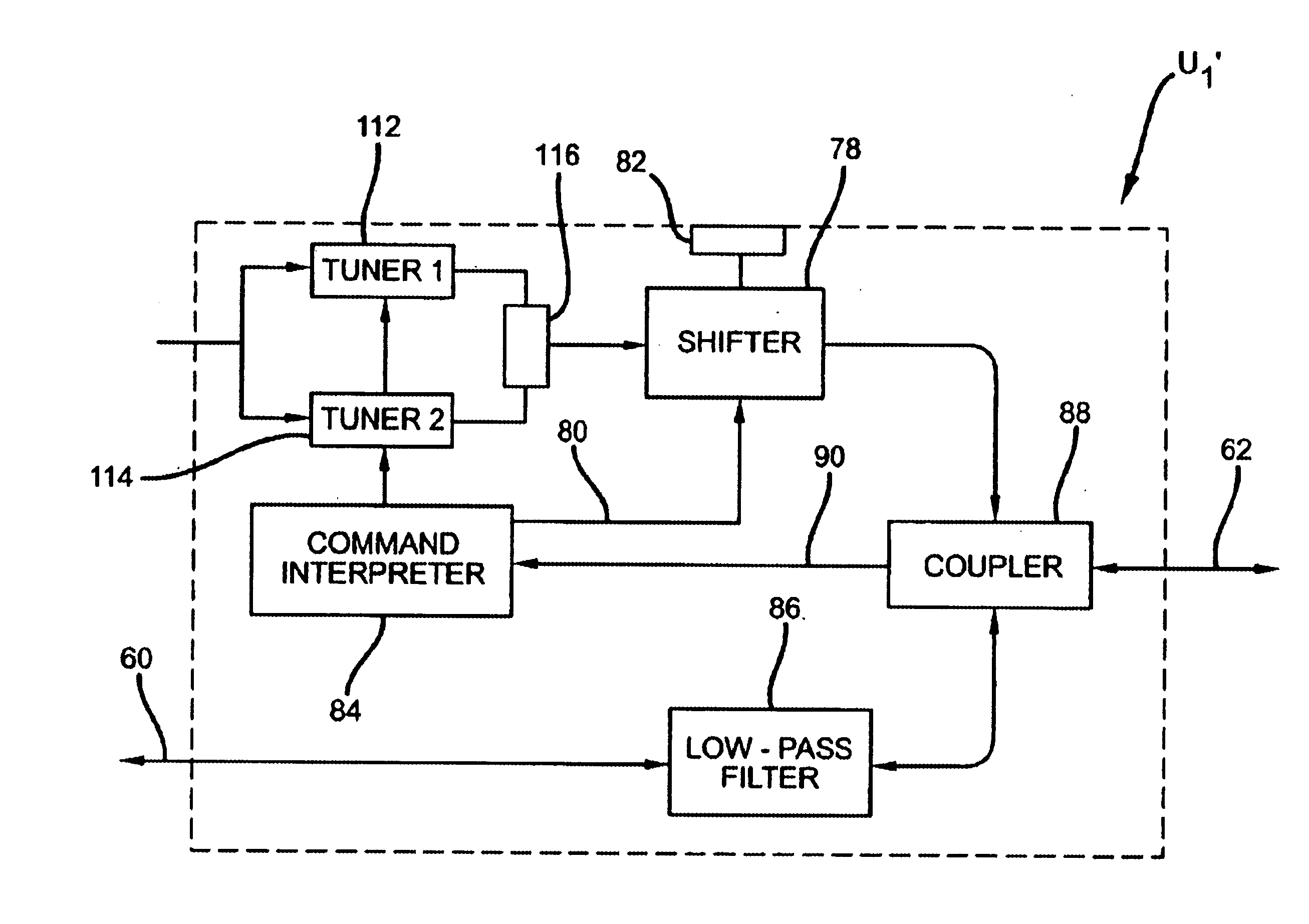
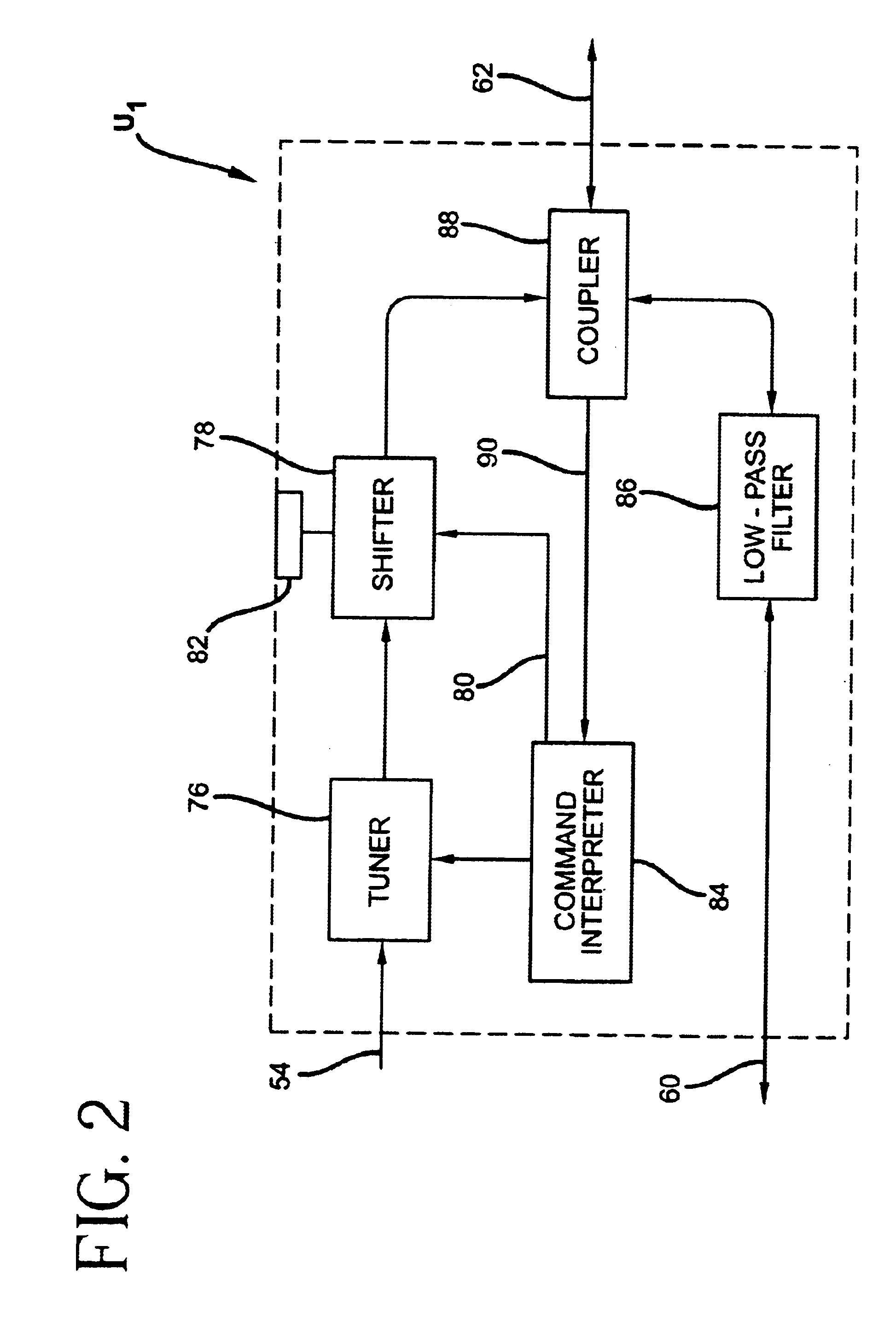
For simplicity in what follows, a partially process oriented description will be adopted, in which a general direction of signal flow suggests an implicit fictitious temporal ordering in the description of static structural relations between system components. It will be readily comprehended that such a description comprises information on the structural, functional and methodic elements of the instant invention, without the necessity of independent description thereof.

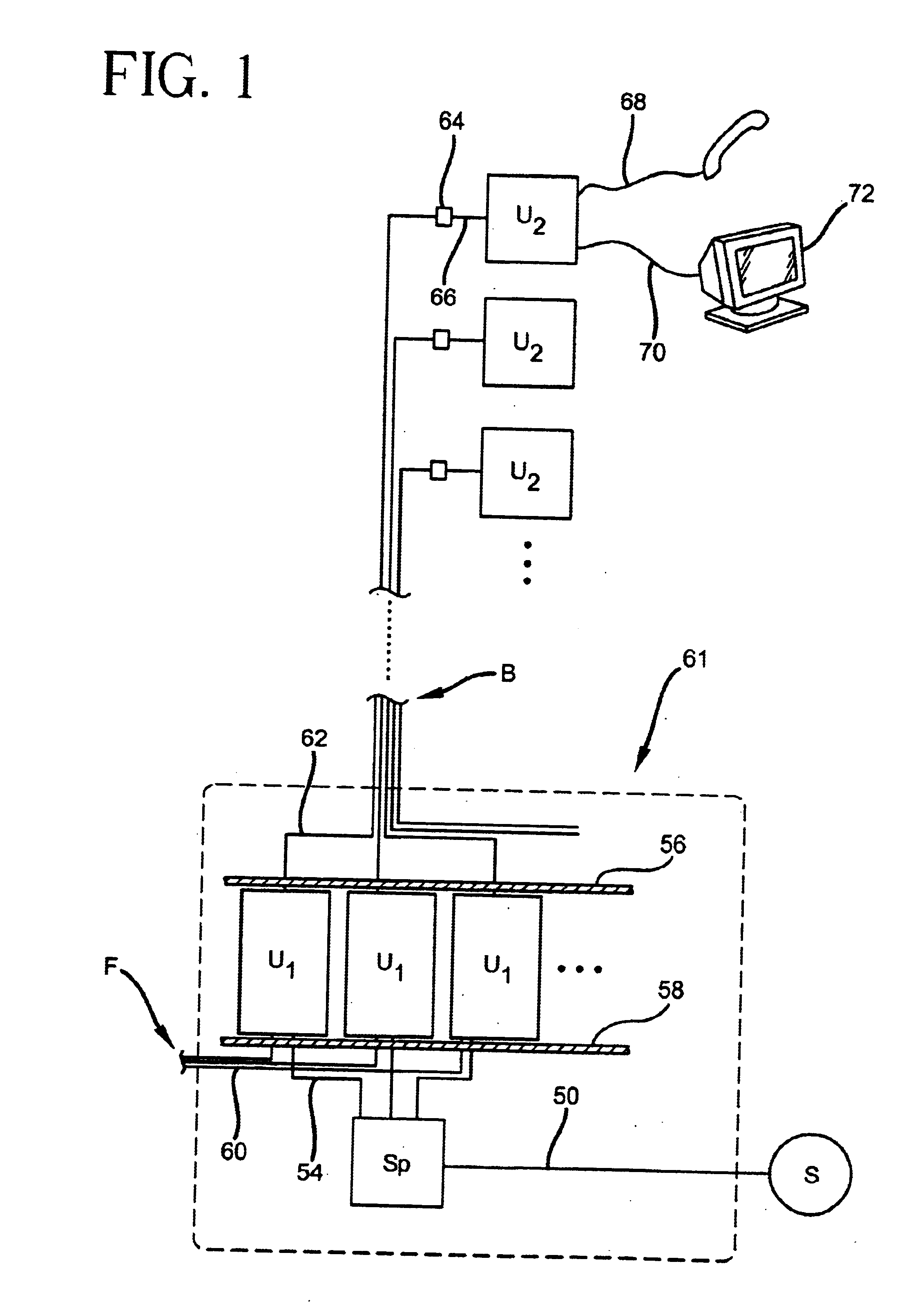
In a first system for the distribution of video program information over subscriber telephone lines, a source or central distribution node S delivers a multiple channel feed into consumer or commercial premises via inside feeder cable 50 (FIG. 1). Source S may comprise an antenna, such as a satellite dish antenna (not illustrated), and related electronics, or a buried coaxial cable (not illustrated). Cable 50 terminates in a splitter Sp, which provides the signal present on cable 50 to a multiplicity of distributor ca...


PUM


Abstract

Video programming signals from a broadband source are distributed on installed telephone wiring to the individual units of a commercial structure or multiple unit dwelling. In all methods and associated devices a first transponder device centrally located in a utility space is paired with a second terminal transponder device located on a telephone subscriber premises. The devices cooperate in converting a video signal into a form suitable for transmission on telephone lines and deconverting that signal into a form suitable for reception by consumer video equipment. The methods and devices discussed differ in placement of the central device, and in the particular method of signal conversion.

Description

FIELD OF THE INVENTIONThis invention relates to a video distribution system and to a related method. More particularly, this invention relates to such a system and method which are useful in multiple unit dwellings.BACKGROUND OF THE INVENTIONIt is well known that ‘cable’ television has largely supplanted broadcast television as the preferred real-time video signal distribution method of choice in the modern home. Compared to broadcast technology, cable distribution offers superior protection against signal degradation and greater available bandwidth. Consumers have expressed a clear preference for programming quantity and variety, and the demand for large channel menus seems likely to persist.Video signals arriving at a multiple dwelling unit building, either by feeder cable or satellite dish or some other source, are advantageously distributed by a local network of coaxial cable terminating in each dwelling unit. These cables provide good shielding, both from outside sources of int...

Claims


Application Information

Patent Timeline
Patent Type & Authority Patents(United States)
IPC IPC(8): H04L5/02H04J1/00H04L5/06H04M11/00H04J1/02H04N7/12
CPCH04N7/108H04N7/106
Inventor TERK, NEIL D.
Owner AUDIOVOX ELECTRONICS
Why Eureka
Try Eureka