Method and apparatus for testing a serial transmitter circuit

a serial transmitter and circuit technology, applied in the direction of line-transmission details, amplitude demodulation, transmission monitoring, etc., can solve the problems of prohibitively expensive, commercial test platforms are typically not capable of operating at comparably high data rates, and it is not possible to use the traditional test technique described

Inactive Publication Date: 2005-03-08
TEXAS INSTR INC
View PDF5 Cites 69 Cited by
  • Summary
  • Abstract
  • Description
  • Claims
  • Application Information

AI Technical Summary

Benefits of technology

From the foregoing, it may be appreciated that a need has arisen for a method and apparatus for facilitating testing of a serializing transmitter circuit at the high serial data rates typical of normal operation, but without requiring the use of a full deserializing receiver circuit or a high-speed test platform. According to the present invention, a method and apparatus are provided to address this need, and include: instructing a serializing transmitter circuit to output a serial bitstream that conforms to a defined bit sequence; sampling a plurality of selected bits in the bitstream to determine a state of each of the selected bits, each such selected bit being separated from other selected bits in the bitstream by at least one nonselected bit; and determining whether the state obtained for each selected bit by sampling conforms to an expected state thereof according to the defined bit sequence.

Problems solved by technology

However, commercial test platforms are typically not capable of operating at comparably high data rates, with the exception of certain high performance test platforms that are prohibitively expensive.
Consequently, it is not possible to use the traditional test technique described above, in which the serial transmitter and receiver on a given integrated circuit are serially coupled to each other for purposes of test.
There is thus an issue of how to effectively test such an integrated circuit, which has a serial transmitter, but no serial receiver.
However, as noted above, they are prohibitively expensive.
However, this can almost double the size of the overall circuitry in the integrated circuit, and thus the physical size of the integrated circuit.
Due to the increased complexity and size, the integrated circuit costs more, and is more susceptible to manufacturing defects and mismatches that reduce the effective yield of chips from the manufacturing process.

Method used


Image

  • Method and apparatus for testing a serial transmitter circuit
  • Method and apparatus for testing a serial transmitter circuit
  • Method and apparatus for testing a serial transmitter circuit

Examples


Embodiment Construction

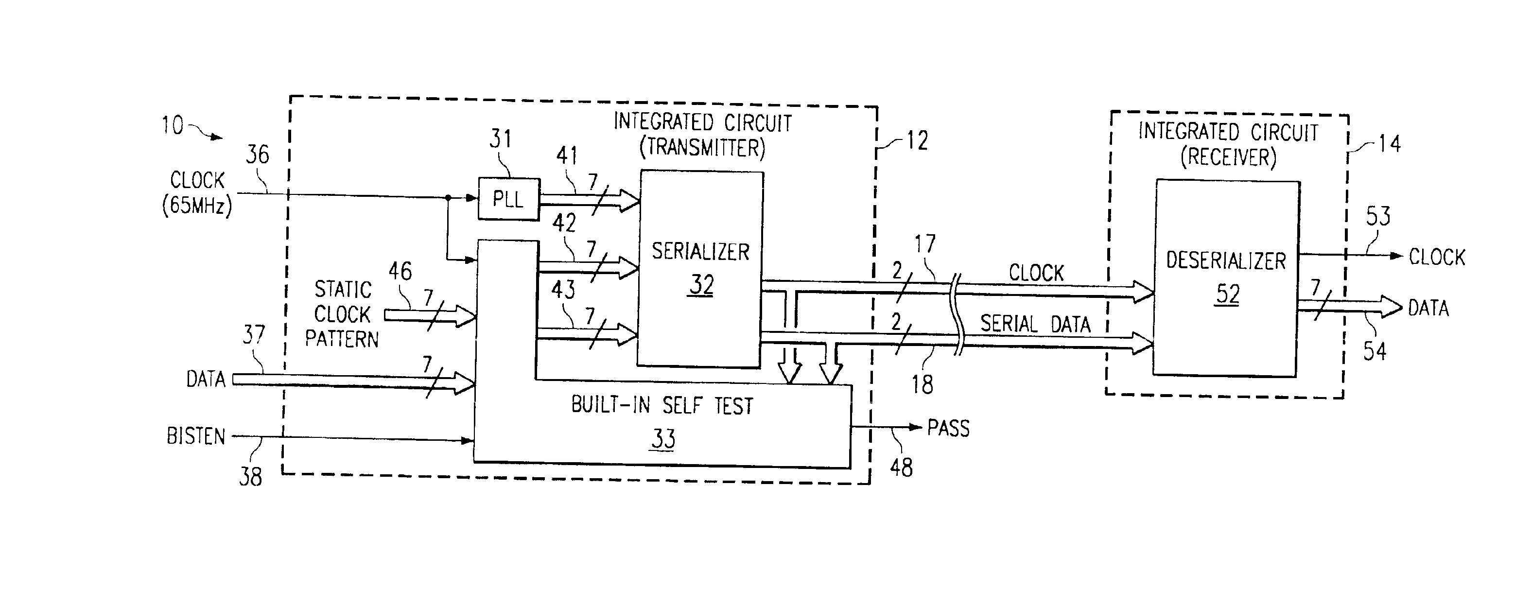
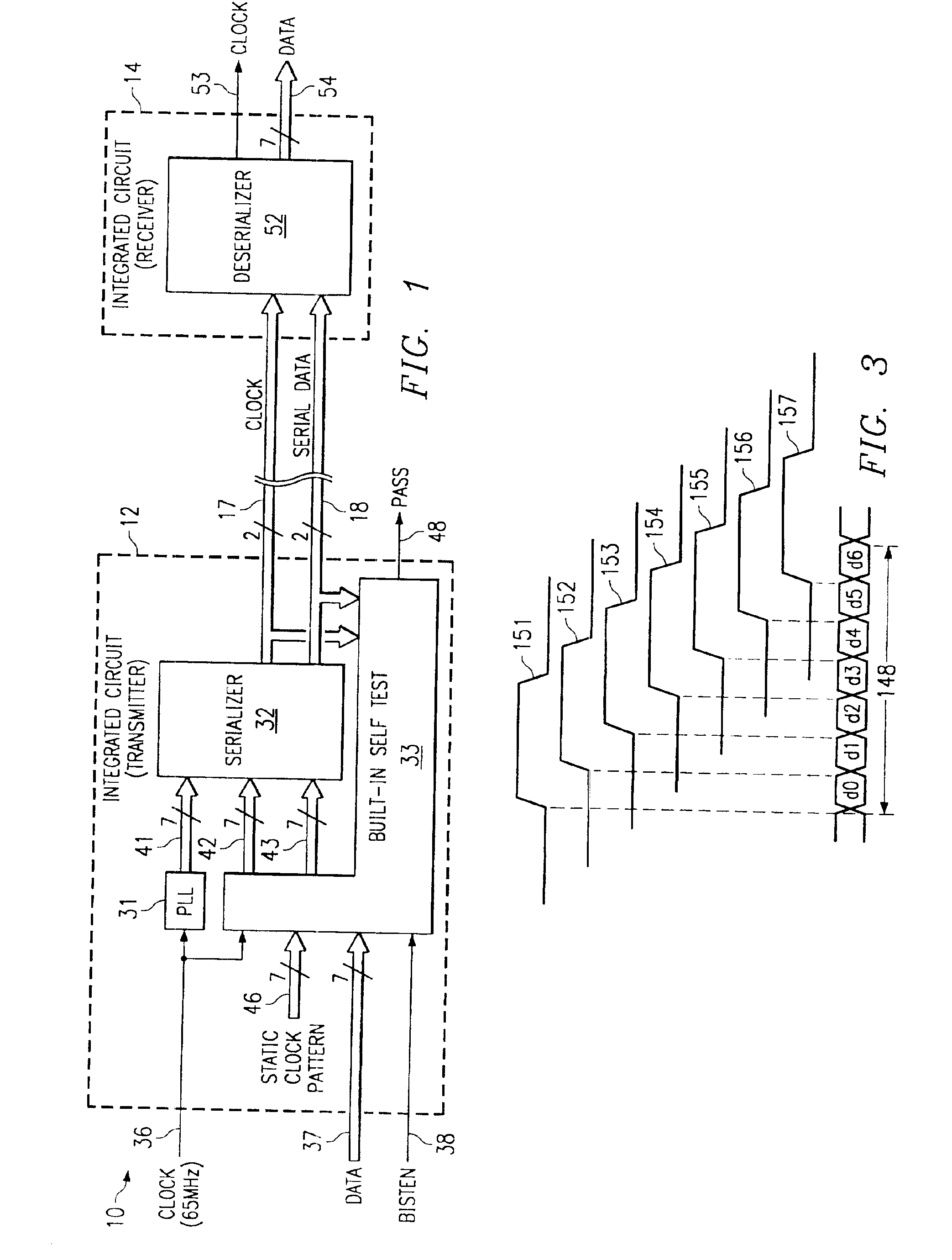
FIG. 1 is a block diagram of a serial communication system 10 which embodies the present invention. The system 10 includes a first integrated circuit 12 which contains a transmitter, a second integrated circuit 14 which contains a receiver, a twisted pair 17 which carries a clock signal from the transmitter in integrated circuit 12 to the receiver in integrated circuit 14, and a further twisted pair 18 which carries serial data from the transmitter in integrated circuit 12 to the receiver in integrated circuit 14.

The embodiment disclosed in FIG. 1 is configured for use in a not-illustrated portable computer, namely a portable computer of the type commonly known as a notebook computer. A notebook computer has a lid pivotly coupled to a case, the case containing the main microprocessor, and the lid containing a liquid crystal display (LCD). When the microprocessor is executing a state-of-the-art program of the type having a graphical user interface (GUI), a substantial amount of displ...


PUM


Abstract

An integrated circuit (12) contains a serializing transmitter, including a phase locked loop (31) that supplies seven clocks (41) with different phases to a serializer circuit (32). The serializer circuit accepts 7-bit words at a parallel input (42), and outputs these words serially in an end-to-end manner on a twisted pair (17), as a clock signal. The serializer circuit also accepts 7-bit words on a further parallel input (43), and transmits them serially in an end-to-end manner on a twisted pair (18), as serialized data. The integrated circuit also includes a built-in self-test circuit (33), which can supply test information to the two parallel inputs of the serializer circuit, and which can monitor the two twisted pairs while the serializer circuit operates at high data rates typical of normal operation, in order to detect any errors introduced by the serializer circuit. The self-test circuit produces a single digital output (48) to indicate whether an error has been detected.

Description

TECHNICAL FIELD OF THE INVENTIONThis invention relates in general to testing of a serial transmitter circuit and, more particularly, to a method and apparatus for testing a serial transmitter circuit at high data rates which are typical of normal operation.BACKGROUND OF THE INVENTIONThere are a variety of applications which use a serial transmitter circuit of the type that receives a series of multi-bit words at a parallel input, and then transmits those words serially in an end-to-end manner at a serial output. During the manufacture of an integrated circuit which includes such a transmitter circuit, the transmitter circuit must be tested for proper operation. Where the transmitter circuit will be used in real-world applications that involve high data rates, it is appropriate to test the transmitter circuit at comparable data rates. However, commercial test platforms are typically not capable of operating at comparably high data rates, with the exception of certain high performance...

Claims


Application Information

Patent Timeline
Patent Type & Authority Patents(United States)
IPC IPC(8): H04B3/46H04L1/24
CPCH04L1/24H04B3/46
Inventor PAYNE, ROBERT FLOYD
Owner TEXAS INSTR INC
Why Eureka
Try Eureka