Method for gradient flow source localization and signal separation

a signal separation and gradient flow technology, applied in speed/acceleration/shock measurement, instruments, surveying and navigation, etc., can solve the problems of large number of parameters, and little knowledge about the problem of localizing and separating multiple broadband sources

Inactive Publication Date: 2005-03-08
THE JOHN HOPKINS UNIV SCHOOL OF MEDICINE
View PDF3 Cites 17 Cited by
  • Summary
  • Abstract
  • Description
  • Claims
  • Application Information

AI Technical Summary

Benefits of technology

The invention, termed gradient flow, is a method of separating and localizing sources of traveling waves that impinge on an array of sensors, without the need of resolving time delays of arrivals as customarily performed in beamforming. Gradient flow converts the problem of separating unknown delayed mixtures of sources into a simpler problem of separating unknown instantaneous mixtures of the time-differentiated sources, obtained by acquiring or computing spatial and temporal derivatives on the array. The linear coefficients in the instantaneous mixture directly represent the delays, which in turn determine the direction angles of the sources. This formulation is...

Problems solved by technology

Yet little is known about the problem of localizing and separating multiple broadband sources.
), but requires a large number of parameters to obtain sufficient temporal resolution...

Method used


Image

  • Method for gradient flow source localization and signal separation
  • Method for gradient flow source localization and signal separation
  • Method for gradient flow source localization and signal separation

Examples


Embodiment Construction

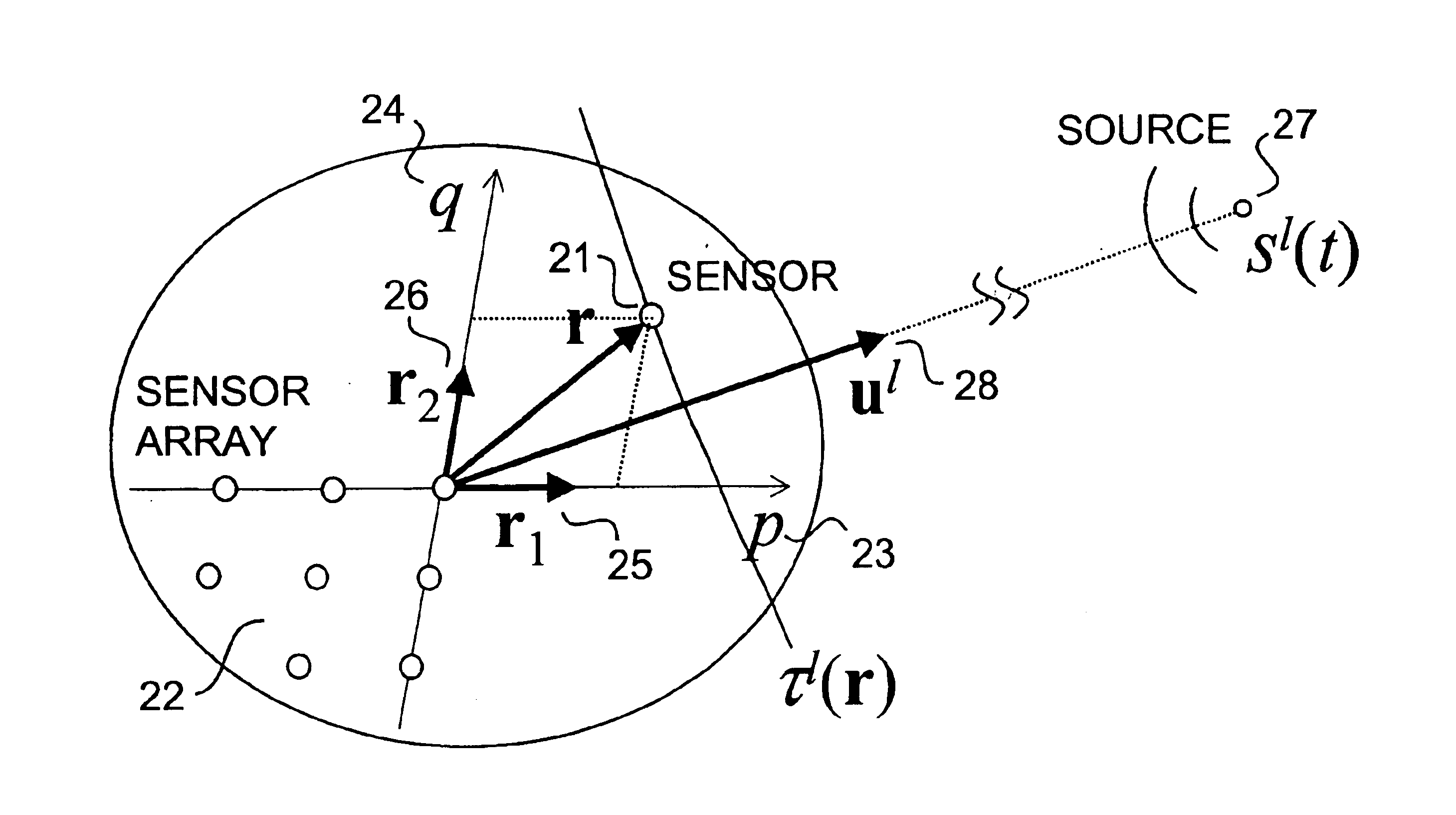
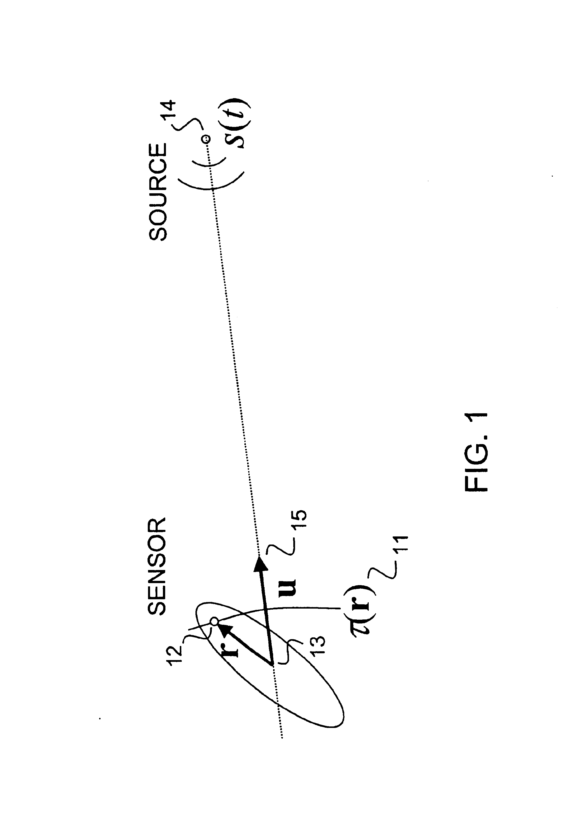
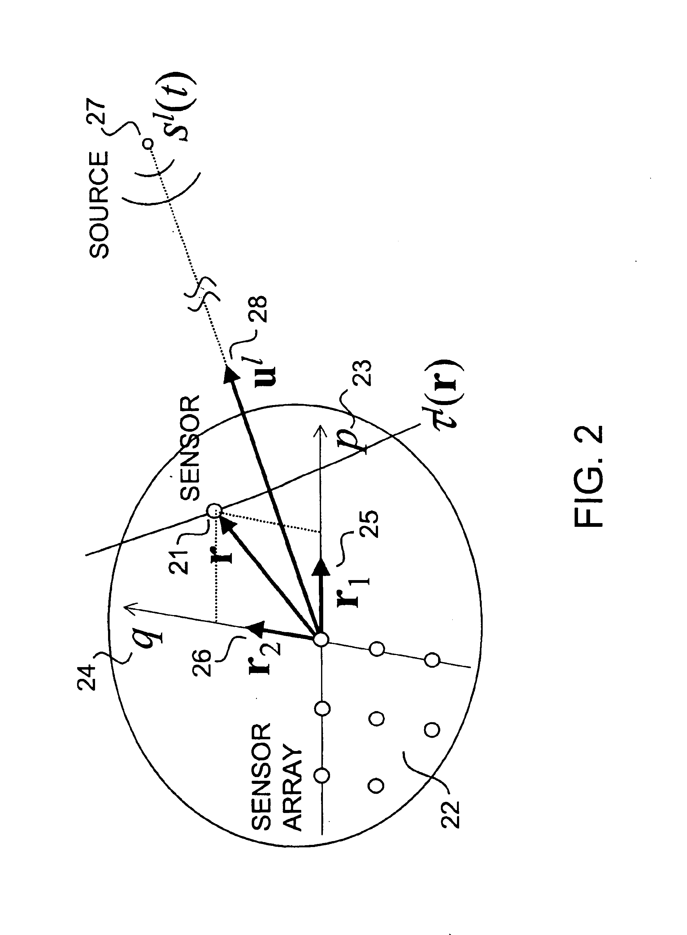
We consider linear mixtures of traveling waves emitted by sources at various locations, and observed over a distribution of sensors in space. The distribution of sensors could be continuous or discrete. In what follows we assume an array of discrete sensors, but the theory applies as well to sensors distributed continuously in space. However, the sources are assumed to be discrete.

The usual approach of the prior art to wideband separation tries to find the sources by combining the received signals at multiple delayed times. This is computationally expensive. The present approach proposed here reduces the problem of separating mixtures of delayed sources to that of separating an instantaneous mixture of signals related to the sources through a succession of time derivatives of increasing order.

Let the coordinate system r be centered in the array so that the origin coincides with the “center of mass” of the sensor distribution. Referring to the geometry in FIG. 1, we define τ(r) 11 as...


PUM


Abstract

A method of separating and localizing sources of traveling waves, by obtaining linearly independent time-differentiated instantaneous observations of the sources, from spatial derivatives of the traveling wave acquired using a distributed sensor or a sensor array. The sources are blindly separated by direct application of (static) independent component analysis on the time-differentiated observations, yielding both the sources and their direction cosines relative to the sensor geometry. The method is suited for arrays of small aperture, with dimensions shorter than the coherence length of the waves. In one preferred embodiment, three sources are separated and localized from differential observations on four coplanar sensors positioned on the corners of a square. Applications include miniature microphone arrays for intelligent hearing aids with adaptive suppression of interfering signals and nonstationary noise, and integrated RF arrays for resolving or localizing multiple users or channels from a base station or mobile unit.

Description

FIELD OF THE INVENTIONThe invention is directed toward separating and localizing a mixture of broadband signals from observation on a compact array of spatially distributed sensors, each signal being generated by a traveling wave source impinging on the array, arriving from different directions. The sensors measure the field resulting from the traveling wave sources, which could be acoustic, sonar, electromagnetic, or possibly other forms of radiation.BACKGROUND OF THE INVENTIONWavefront sensing in space for localizing sound has been in practice since the pioneering work by Blumlein (as described in British Patent 394325 to Blumlein, “Improvements in and Relating to Sound-Transmission, Sound-Recording and Sound-Reproducing Systems”, 1933), a precursor to the advances in binaural signal processing that we know today. The direction of a traveling wave can be inferred directly by sensing spatial differentials on a sub-wavelength scale, a principle exploited in biology, e.g., by the Sar...

Claims


Application Information

Patent Timeline
IPC IPC(8): G01V1/28
CPCG01V1/28G01V2210/20
Inventor CAUWENBERGHS, GERTSTANACEVIC, MILUTINZWEIG, GEORGE
Owner THE JOHN HOPKINS UNIV SCHOOL OF MEDICINE
Why Eureka
Try Eureka