Component mounting method

a technology of component mounting and mounting method, which is applied in the direction of metal working apparatus, printed circuit manufacturing, manufacturing tools, etc., can solve the problems of increasing machine space and costs, xy table incorporation mechanical error, and series nozzle type requiring greater alignment length, so as to improve the efficiency of component mounting and break down the types of applicable components

Inactive Publication Date: 2005-03-15
PANASONIC CORP
View PDF13 Cites 19 Cited by
  • Summary
  • Abstract
  • Description
  • Claims
  • Application Information

AI Technical Summary

Benefits of technology

[0012]The present invention aims to offer a space-saving and compact component mounter and mounting method which allows to increase the mounting efficiency by improving the feasibility of simultaneous pickup of several components.
[0013]The present invention also aims to offer a component mounter and mounting method that enables processing of highly precise calibration data by appropriately placing a board recognition camera with respect to a transfer head to which two or more nozzles are provided.
[0014]The present invention further aims to offer a component mounter and mounting method which improves the mounting efficiency by broadening the types of applicable components.

Problems solved by technology

However, the moving shafts composing the XY table incorporate mechanical error caused by pitch error of the ball screw.
However, a conventional transfer head as described above has the following disadvantages in mounter structure and mounting efficiency.
First, the series nozzle type requires greater alignment length with increasing number of nozzles.
This leads to a longer horizontal movement stroke for moving the transfer head within the mounter, increasing machine space and costs.
In addition, a larger number of nozzles unavoidably results in buildup of pitch error between suction nozzles.
Larger pitch error causes more frequent suction errors while vacuum-holding two or more components picked up at the same time from the component feeder carriage (multiple parts feeders) by two or more suction nozzles.
The resulting failure of simultaneous component pickup may reduce mounting efficiency.
This lower feasibility of simultaneous pickup is also a disadvantage of the rotary transfer head.
However, it is difficult to efficiently dispose two or more suction nozzles for components with different sizes and shapes in a conventional multi-nozzle transfer head.
This restricts the types of components that can be mounted using the same mounter, impeding the improvement of mounting efficiency.
Third, a multi-nozzle transfer head also requires the aforementioned calibration process.
However, a complete set of calibration data may not be obtainable depending on where the camera is positioned on the series nozzle transfer head when the board recognition camera installed in the series nozzle transfer head is used for calibration.

Method used


Image

  • Component mounting method
  • Component mounting method
  • Component mounting method

Examples


Embodiment Construction

[0049]A preferred embodiment of the present invention is described below with reference to drawings.

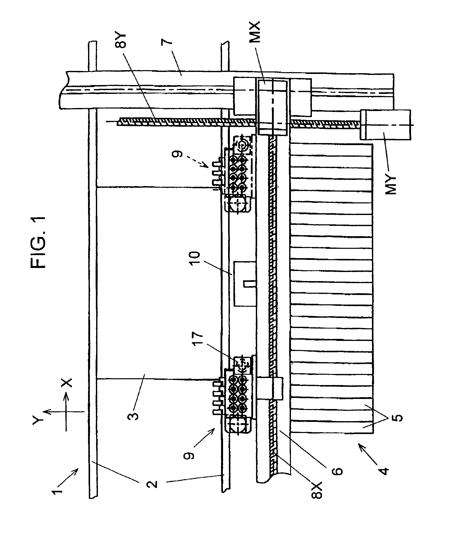
[0050]FIG. 1 is a plan view of a component mounter in the preferred embodiment of is the present invention.

[0051]First, the overall structure of the component mounter is described with reference to FIG. 1.

[0052]In FIG. 1, rail 2 is provided on component mounter 1. Rail 2 transports and positions board 3 onto which components are mounted. Component feeder carriage 4 is disposed at the side of rail 2. Tape feeders 5, which are multiple parts feeders, are set parallel to each other in feeder carriage 4.

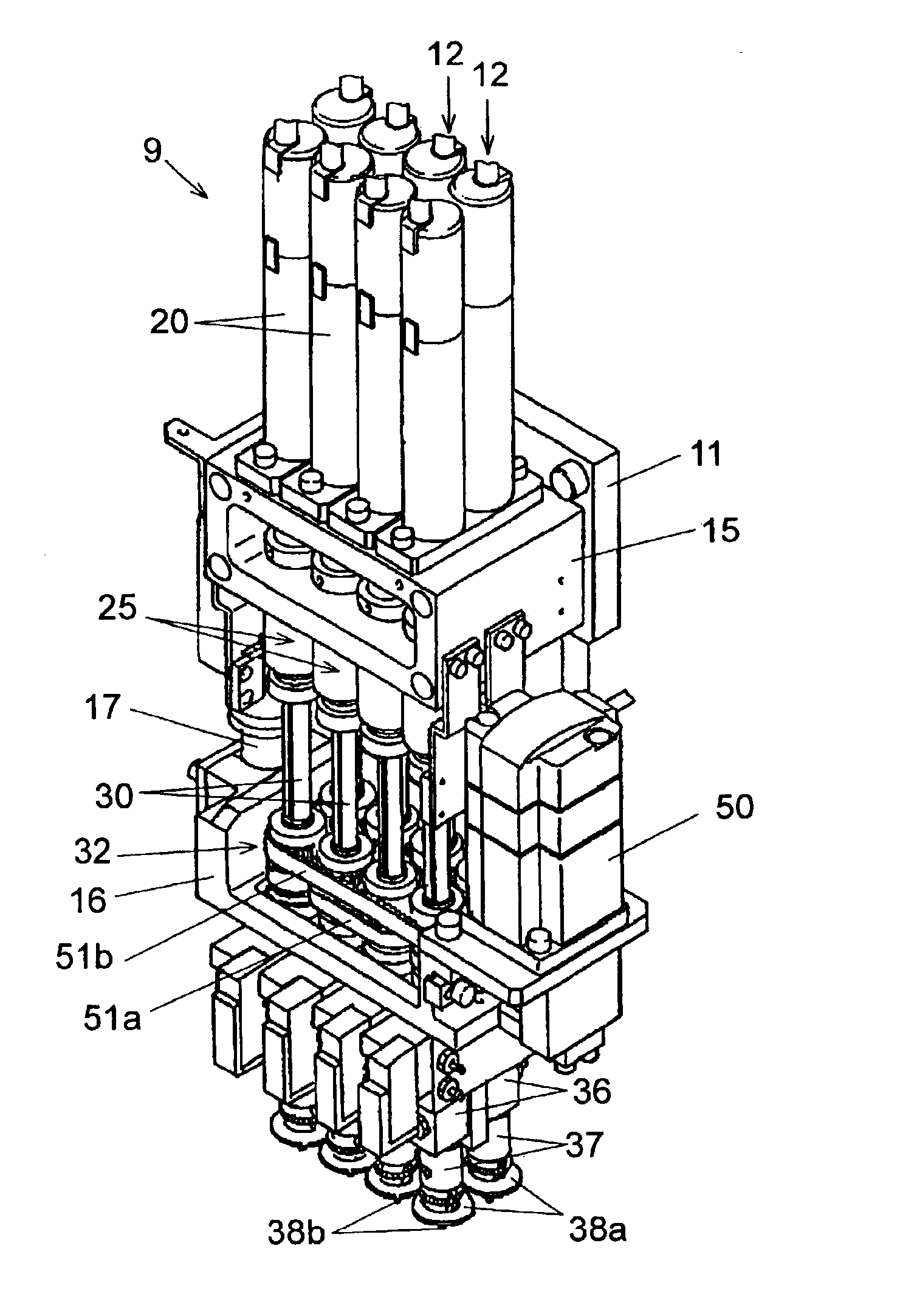
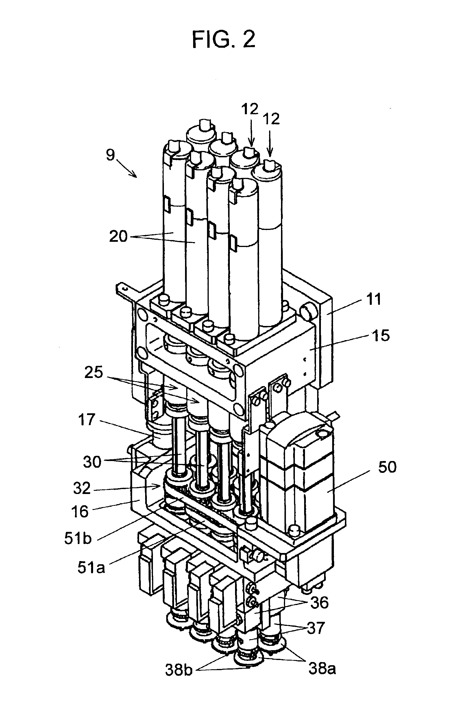
[0053]X-axis table (X table) 6 and Y-axis table (Y table) 7 are disposed over feeder carriage 4 and rail 2. X table 6 is equipped with feeding screw 8X and driving motor “MX.” Y table 7 is equipped with feeding screw 8Y and driving motor “MY.” X table 6 moves in the Y direction when Y motor “MY” is driven, and Y table 7 moves in the X direction when X motor “MX” is driven. Transfer head 9 ...


PUM

PropertyMeasurementUnit
sizesaaaaaaaaaa
mechanical erroraaaaaaaaaa
timeaaaaaaaaaa

Abstract

A component mounter which picks up components from two or more tape feeders aligned in a component feeder carriage, and mounts them a board. Suction nozzles for vacuum-holding components are disposed on the transfer head at a predetermined basic pitch in the X direction (tape feeders alignment direction) to form a nozzle line. Two or more nozzle lines are aligned in the Y direction (perpendicular to the X direction). These suction nozzles pick up two or more components from the tape feeders simultaneously, enabling to reduce the space required for installing the mounter and making the mounter more compact. Increased feasibility of simultaneous pickup of several components also improves mounting efficiency.

Description

[0002]This application is a divisional of U.S. patent application Ser. No. 09 / 885,887 filed Jun. 20, 2001, now U.S. Pat. No. 6,606,790.FIELD OF THE INVENTION[0003]The present invention relates to component mounters and mounting methods for mounting, for example, electronic components on a board.BACKGROUND OF THE INVENTION[0004]A component mounter for mounting electronic components such as semiconductors on a board is equipped with a component feeder carriage in which numerous parts feeders such as tape feeders for storing components are aligned.[0005]The component mounter repeats the mounting operation of picking up components from these parts feeders using its transfer head, and placing them on the board. In order to improve the efficiency of this mounting operation, multi-nozzle transfer head, in which two or more suction nozzles for holding components are aligned, is often used. Conventional alignment of suction nozzles in the multi-nozzle transfer head includes the series nozzle...

Claims


Application Information

Patent Timeline
Patent Type & Authority Patents(United States)
IPC IPC(8): H05K13/04
CPCH05K13/0413H05K13/041Y10T29/5193Y10T29/53Y10T29/49131Y10T29/4913Y10T29/53183Y10T29/53178Y10T29/53022Y10T29/53191H05K13/0408
Inventor HIDESE, WATARU
Owner PANASONIC CORP
Why Eureka
Try Eureka