Anti-rotation guide for a deactivation hydraulic valve lifter

a technology of anti-rotation guide and hydraulic valve lifter, which is applied in the direction of mechanical equipment, engine components, machines/engines, etc., can solve the problems of affecting the hydraulic recovery of the lifter's hydraulic plunger assembly, and unable to readily apply remedy to the deactivation lifter assembly. , to achieve the effect of minimal friction resistan

Inactive Publication Date: 2005-03-15
DELPHI TECH IP LTD
View PDF15 Cites 29 Cited by
  • Summary
  • Abstract
  • Description
  • Claims
  • Application Information

AI Technical Summary

Benefits of technology

An advantage of the present invention is that the anti-rotation retains the lifter prior to engine installation.
A further advantage of the present invention is that, once installed, the anti-rotation guide tightly constrains the deactivation lifter rotationally but loosely constrains t

Problems solved by technology

Unless suitably guided by an anti-rotation mechanism, the lifter may rotate in its bore during reciprocation, thereby undesirably misaligning its follower from the associated cam lobe.
Because the guide snuggly grips each lifter, a significant frictional drag is created between the lifter and guide which can impede hydraulic recovery of the lifter's hydraulic plunger assembly after being drained of oil during shutdown.
However, because of size constraints placed on the deactivation lifter design

Method used


Image

  • Anti-rotation guide for a deactivation hydraulic valve lifter
  • Anti-rotation guide for a deactivation hydraulic valve lifter
  • Anti-rotation guide for a deactivation hydraulic valve lifter

Examples


Embodiment Construction

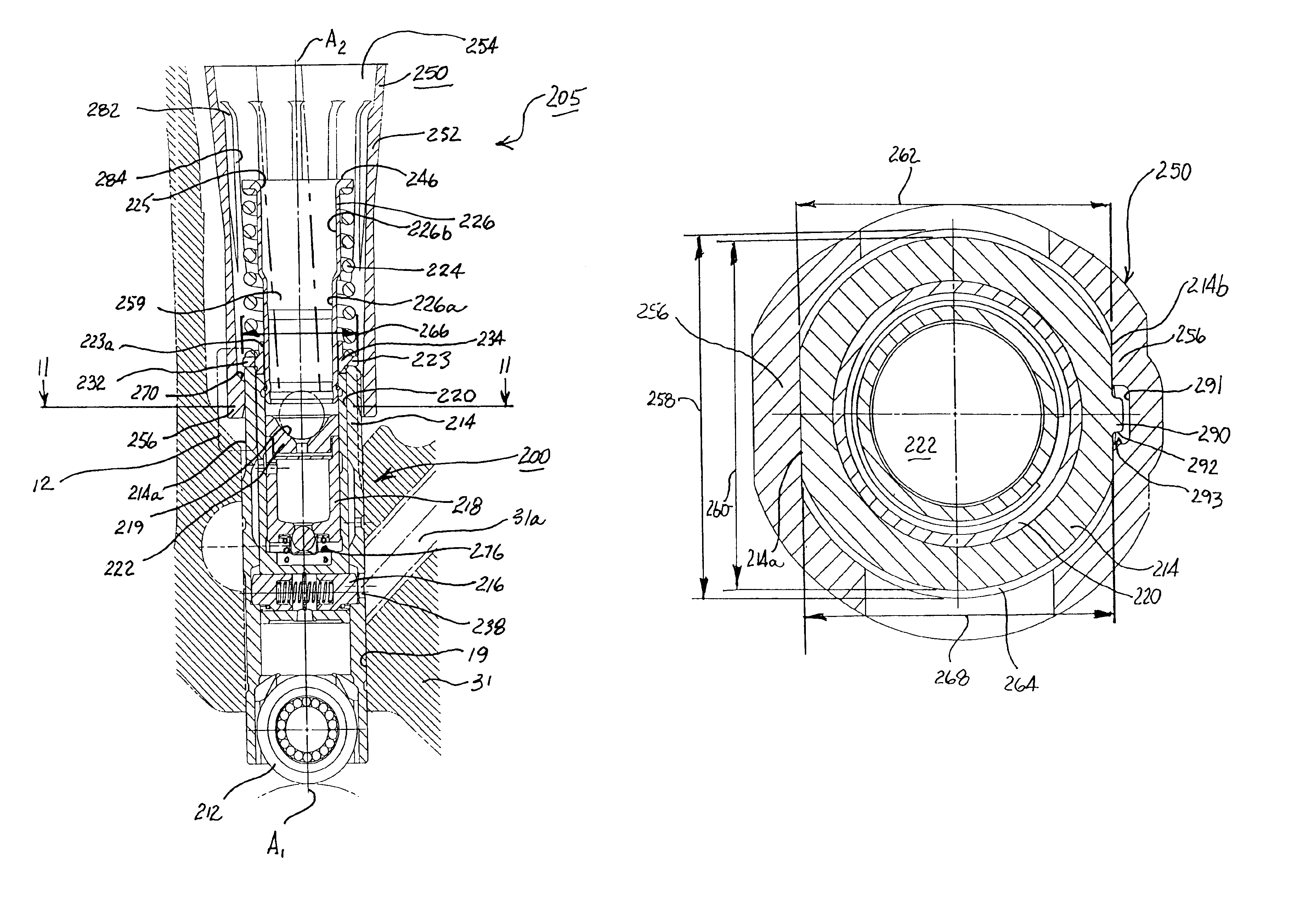
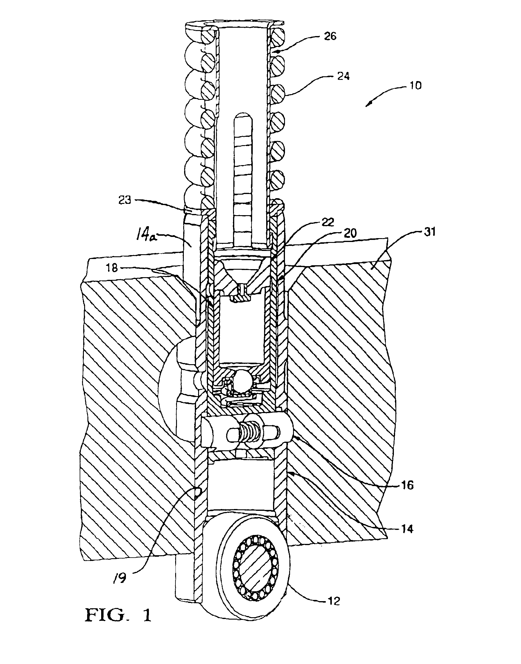
Referring to the drawings and particularly to FIG. 1 herein, a deactivation roller hydraulic valve lifter (DRHVL) 10, as disclosed in U.S. Pat. No. 6,513,470, includes roller 12, lifter body 14, deactivation pin assembly 16, plunger assembly 18, pin housing 20, pushrod seat assembly 22, spring seat 23, lost motion spring 24, and spring tower 26. As shown, DRHVL 10 is inserted into its respective bore 19 of engine 31 for engagement with the engine camshaft (not shown).

Roller 12, associated with body 14 of DRHVL 10, rides on a lobe of the camshaft and translates the rotary motion of the camshaft to vertical motion of lifter body 14. An anti-rotation guide (not shown in FIG. 1) secured to the engine fits around the lifter body to prevent the lifter from rotating during reciprocation. Deactivation pin assembly 16 normally engages lifter body 14 and transfers the vertical reciprocation of lifter body 14 to pin housing 20. Vertical reciprocation is, in turn, transferred to plunger assembl...


PUM


Abstract

An anti-rotation guide for a deactivation hydraulic valve lifter for an internal combustion engine. The guide includes a through bore accommodating of a hydraulic valve lifter and is sized such that the outer end of the lifter may be inserted into the through bore of the guide. The guide is securable to the engine such that the lifter is reciprocable within the guide. The guide is provided with two opposing keepers for mating with corresponding flats on the lifter to prevent rotation of the lifter. Further, a keyway means is provided in the guide and lifter to prevent the lifter being inserted into the guide 180° from the correct orientation.

Description

TECHNICAL FIELDThe present invention relates to hydraulic valve lifters for use with internal combustion engines, more particularly, to an anti-rotation guide which prevents rotation of a deactivation hydraulic valve lifter in a push-rod internal combustion engine, and even more particularly, to an anti rotation guide that minimizes frictional loss between the guide and the lifter body of a deactivation hydraulic valve lifter.BACKGROUND OF THE INVENTIONCylinder deactivation during at least a portion of the combustion process is a proven method by which fuel economy can be improved. With fewer cylinders performing combustion, fuel efficiency is increased and the amount of pollutants emitted from the engine is reduced. A known method of providing cylinder deactivation in a push rod engine is by using a deactivation mechanism in the hydraulic valve lifter.A hydraulic valve lifter, whether of the deactivating or non-deactivating type, slides reciprocally in an engine bore. The lifter en...

Claims


Application Information

Patent Timeline
IPC IPC(8): F01L1/20F01L1/14F01L1/245F01L13/00
CPCF01L1/146F01L1/245F01L13/0005Y10T74/2107F01L2105/00F01L2305/00
Inventor SPATH, MARK J.
Owner DELPHI TECH IP LTD
Why Eureka
Try Eureka