Freestanding portable splatter shield

Inactive Publication Date: 2005-03-15
HAEMERLE RICHARD R
View PDF28 Cites 26 Cited by
  • Summary
  • Abstract
  • Description
  • Claims
  • Application Information

AI Technical Summary

Benefits of technology

The present invention relates to a splatter shield which includes a central panel and two end panels that are selectively foldable in an overlying relationship to the central panel for storage and are positionable at a multitude of different angular orientations extending outwardly from the central panel for use in a freestanding manner. A stove or other kitchen appliance such as a wok, electric skillet, mixer and so forth may be positioned in the space between the end panels and central panel providing a shield on three sides of a work area. The central panel may comprise a wall member having extension members associated therewith which are movably mounted thereto for adjusting the length of the central panel in a selective manner. The end panels are hingedly connected to the central panel or to the extension members and preferably the hinged connection is accomplished through the use of integral hinge members such as flexible non-mechanical anamorphic type hinges, although other hinge elements and hinge arrangements would likewise work equally as well. The hinge members may be constructed such that the two end panels will lie generally flat and parallel to the central panel in an overlaying relationship when the end panels are folded into their storage position. Retention members may also be provided to fix the moveable extension members in a selected position relative to the central panel. The splatter shield is preferably made of a molded polymeric material for lightness in weight, easy cleaning and imperviousness to degradation by cleaners and food products.
The present splatter shield therefore represents

Problems solved by technology

This device does not protect the stove or kitchen area from spattering to the sides or rear of the stove or other areas.
The screens are retractable into the frame associated with the stove but do not protect a spattering to the rear or other locations relative to the stovetop.
While portable and usable at various locations, the accordion style pleated shield is awkward, difficult to manipulate and maneuver, difficult to position in certain work areas, and difficult to clean and maintain sanitary because of its pleated construction.
Also, importantly, the end panels are not angularly adjustable relative to the central back panel.
This makes it difficult to provide for a somewhat universally adaptable sp

Method used


Image

  • Freestanding portable splatter shield
  • Freestanding portable splatter shield
  • Freestanding portable splatter shield

Examples


Embodiment Construction

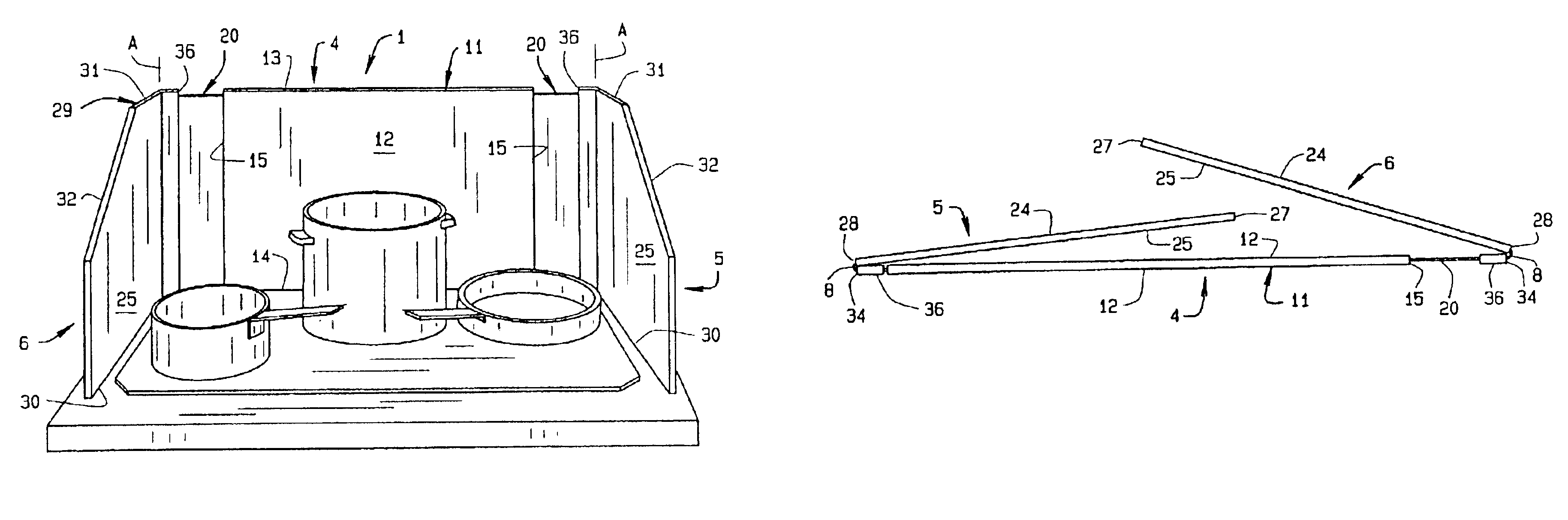
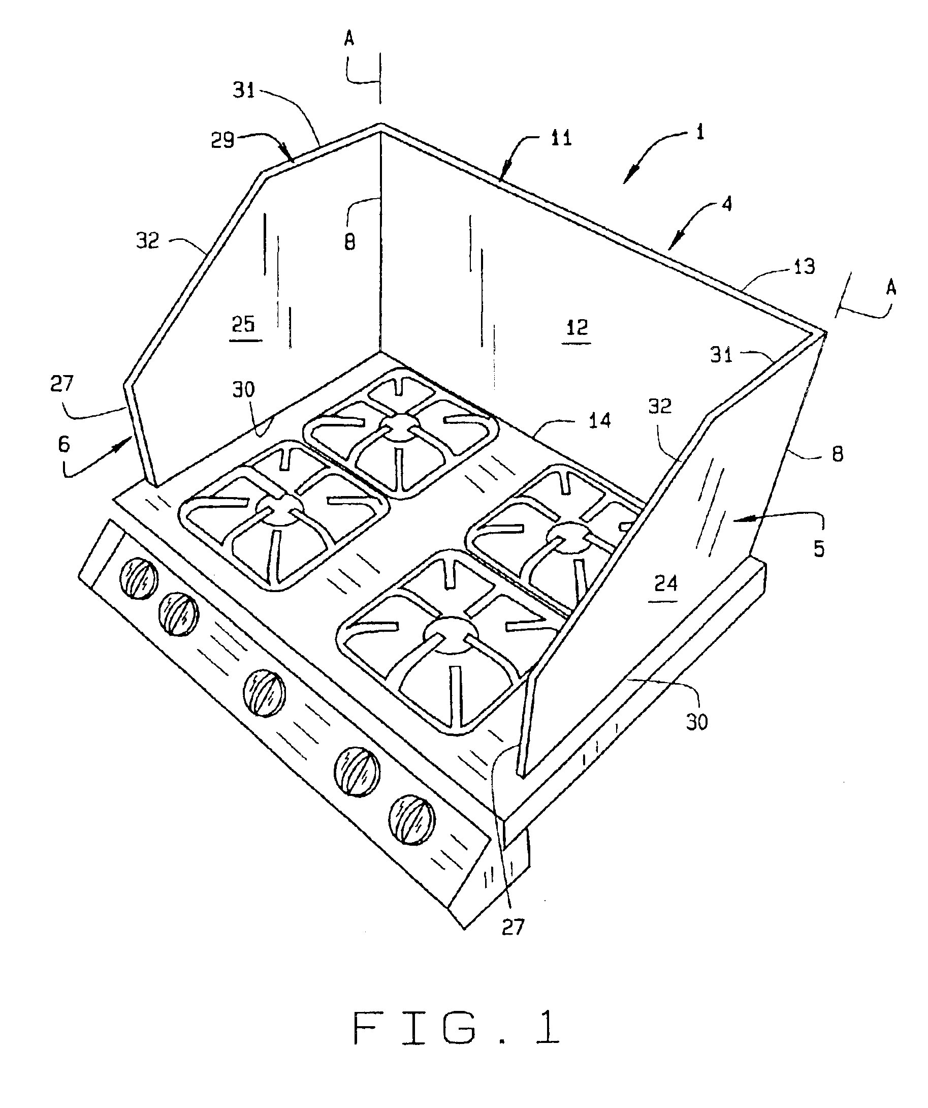
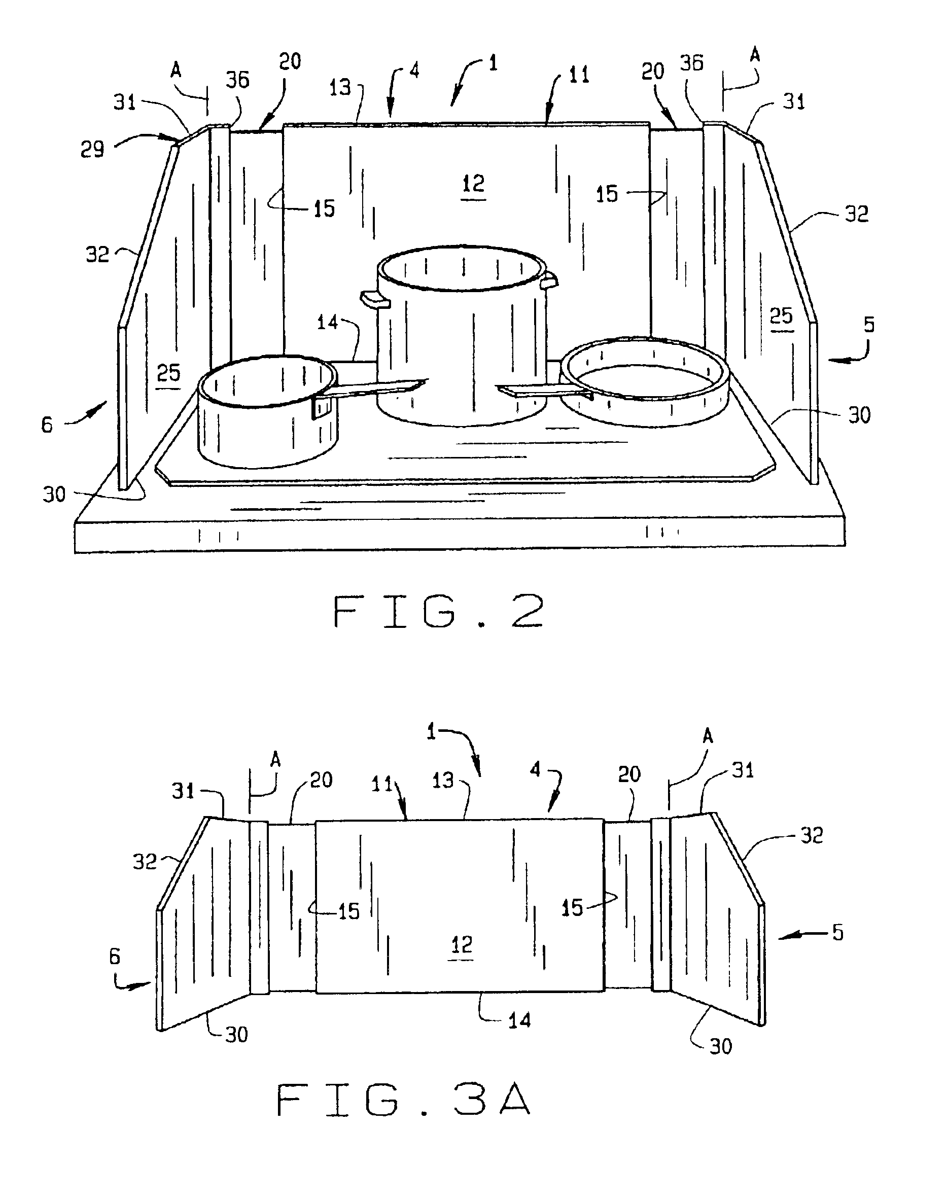
Referring to the drawings more particularly by reference numbers wherein like numerals refer to like parts, the reference number 1 in FIGS. 1, 2, 3A, 3B, 4-7 and 9-11 identifies one embodiment of a splatter shield constructed in accordance with the teachings of the present invention. The present splatter shield 1 can be used in a variety of locations in a freestanding mode as best illustrated in FIGS. 1 and 2 and can be stored in a collapsed or folded condition as best illustrated in FIG. 5. The splatter shield 1 includes a central panel 4 and a pair of end panels 5 and 6, all of which are preferably generally planar. The end panels 5 and 6 are hingedly connected to the central panel 4 such as by the hinge members 8. The end panels 5 and 6 are angularly movable relative to the central panel 4 about the hinge members 8 whereby the end panels 5 and 6 may be selectively positioned extending outwardly from the central panel 4 as best illustrated in FIG. 1 to provide a freestanding splat...


PUM


Abstract

A freestanding splatter shield for use in kitchens and other food processing work areas including a central panel and first and second end panels pivotally attached to the respective opposite end portions of the central panel. The first and second end panels are selectively positionable at a plurality of different angular orientations relative to the central panel to accommodate different work areas and are foldable or collapsible into a compact storage position wherein the first and second end panels lie substantially parallel to the central panel in overlaying relationship thereto. In addition, the present splatter shield may include at least one extension member operatively associated with the central panel for selectively increasing and decreasing the overall length of the central panel.

Description

BACKGROUND OF INVENTIONThe present invention relates generally to splatter guards and shield assemblies and, more particularly, to an all purpose portable, freestanding, and adjustable splatter shield for use in kitchens and other areas.Splatter shields for use in kitchens are well known. They are typically constructed to be used on or about a stovetop and attach permanently or semi-permanently to the stove. An example of such a splatter shield can be found in U.S. Pat. No. 5,351,673. This device is referred to as a spatter guard for use with a recreational vehicle (RV) stove. It attaches to a hinged cover that overlies the burners on the stove and can only be used when the burner cover is in an elevated position exposing the burners for use. The spatter guard includes two wings each positionable at opposite sides of the stove, each wing being attachable to an opposite end of the burner cover. Such a spatter guard is dedicated for use with a stove having a burner cover and on its ow...

Claims


Application Information

Patent Timeline
IPC IPC(8): F24C15/12
CPCF24C15/12
Inventor HAEMERLE, RICHARD R.
Owner HAEMERLE RICHARD R
Why Eureka
Try Eureka