Method of locating a calibration patch in a reference calibration target

a calibration target and reference technology, applied in the field of photography, can solve the problems of difficult to locate patches with adequate accuracy in digital images, require exposure apparatus, and difficult to locate patches, etc., and achieve the effect of optimizing the use of the available area

Inactive Publication Date: 2005-03-15
MONUMENT PEAK VENTURES LLC
View PDF31 Cites 42 Cited by
  • Summary
  • Abstract
  • Description
  • Claims
  • Application Information

AI Technical Summary

Benefits of technology

The method of the present invention has the advantage that no extra area on the photographic element is occupied by fiducial marks, thereby optimizing the use of the available area, since the standard two-dimensional barcode

Problems solved by technology

Unfortunately, exposures which produce reference calibration patches that are of low contrast with respect to their background, such as obtained upon development of isolated low exposure areas on a color negative film, are difficult to locate with adequate accuracy in a digital image.
All th

Method used


Image

  • Method of locating a calibration patch in a reference calibration target
  • Method of locating a calibration patch in a reference calibration target
  • Method of locating a calibration patch in a reference calibration target

Examples


Embodiment Construction

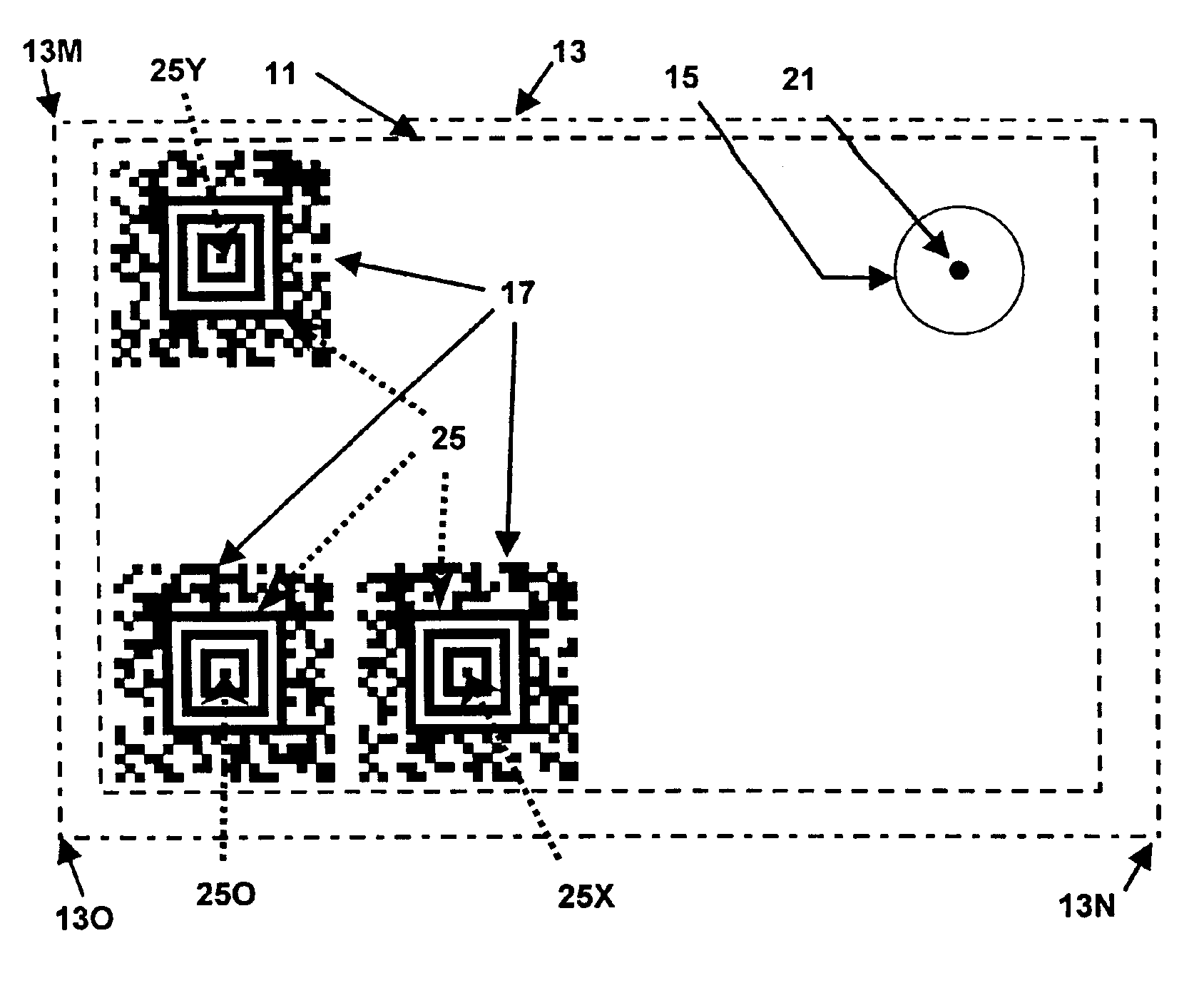
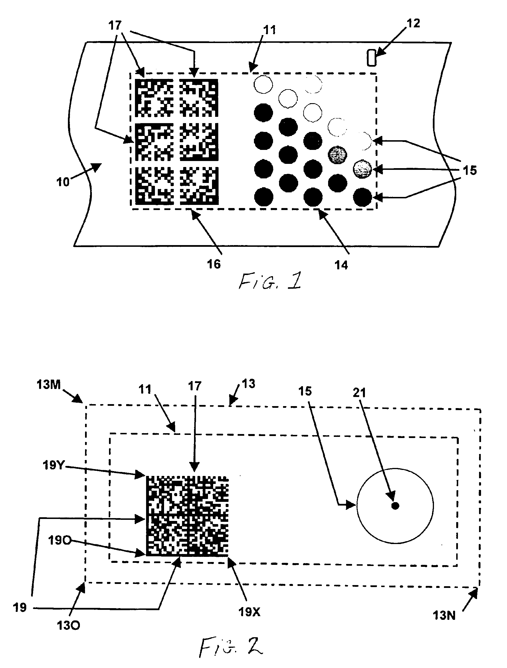
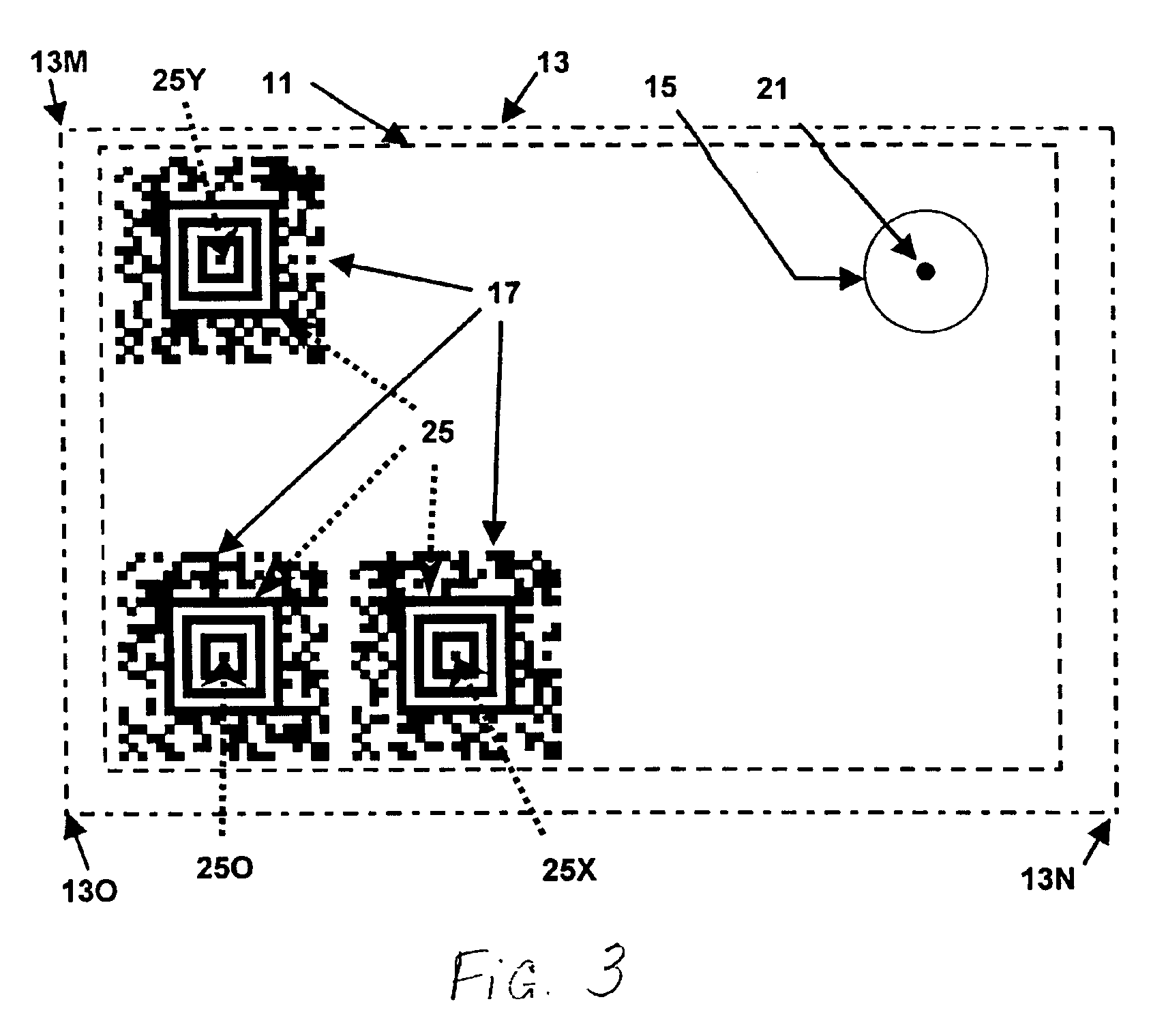
An array of reference calibration patches are formed on a photographic element using exposures delivered using any of a variety of exposure modulation devices, preferably using a light source, an integrating chamber, and a fiber optic array with attenuating filters for determining exposure and an imaging head containing an array of lenses and field stops, each fiber exposing one reference calibration patch, as disclosed in copending U.S. Ser. No. 09 / 635,389, now U.S. Pat. No. 6,407,767 issued Jun. 18, 2002, by Bigelow et al. entitled Apparatus For Exposing Sensitometric And Bar Code Data Onto Photosensitive Media. The number of reference calibration patches in the array is a function of the application. We prefer 23 patches for APS photographic film. A photographic element includes at least a base with a photosensitive layer that is sensitive to light to produce a developable latent image. The photosensitive layer may contain conventional silver halide chemistry, or other photosensi...


PUM


Abstract

A method of locating a reference calibration patch on a photographic element, that includes the steps of: exposing the photographic element to form a latent image of a reference calibration target having a two dimensional barcode symbol with a finder feature and a reference calibration patch having a known spatial relation to the finder feature of the two-dimensional barcode symbol; processing the photographic element to form a density image from the latent image; scanning the density image to produce a digital image; locating the finder feature of the two-dimensional barcode symbol in the digital image; and locating the reference calibration patch relative to the finder feature in the digital image.

Description

FIELD OF THE INVENTIONThe present invention relates to photography, and more particularly to photographic film having reference calibration patches and data.BACKGROUND OF THE INVENTIONThe use of a sequence of reference calibration patches exposed on a roll of film to enable better exposure control during optical printing is known in the art. See for example U.S. Pat. No. 5,767,983 issued Jun. 16, 1998 to Terashita entitled Color Copying Apparatus for Determining Exposure Amount from Image Data of an Original Image and a Reference Image. The use of calibration patches has also been shown to be useful in determining correction values for scanned film data used in digital printing. See for example U.S. Pat. No. 5,667,944 issued Sep. 16, 1997 to Reem et al. entitled Digital Process Sensitivity Correction; and U.S. Pat. No. 5,649,260, issued Jul. 15, 1997 to Wheeler et al. entitled Automated Photofinishing Apparatus. It is also known to provide barcode data relating to film type and fram...

Claims


Application Information

Patent Timeline
IPC IPC(8): G03C11/02G03C11/00H04N1/00G03B27/32G03C1/00G03B27/73
CPCG03C11/02H04N1/00002H04N1/00015H04N1/00063H04N1/00045H04N1/00053H04N1/00031
Inventor KEECH, JOHN T.SPENCE, JOHN P.
Owner MONUMENT PEAK VENTURES LLC
Why Eureka
Try Eureka