
Compressor

a compression compressor and compression space technology, applied in the field of compression compressors, can solve the problems of reducing the compression efficiency of the piston compressor, increasing the generation of vibration and noise, and the difficulty of manufacturing of the scroll compressor, so as to achieve the effect of sufficient dimension of the compression space and improving the compression efficiency

Inactive Publication Date: 2005-03-15
MAENG HYUK JAE
View PDF8 Cites 10 Cited by
  • Summary
  • Abstract
  • Description
  • Claims
  • Application Information

AI Technical Summary

Benefits of technology

"The present invention provides a compressor with a cylinder-shaped compression chamber, a rotor with pressing pins, and a rotary pressing member with two wings that improve compression efficiency and prevent damage to the compressor. The compressor can compress a medium by varying the dimension of the compression space and maintaining the sealed condition of the compression chamber. The technical effects of the invention are improved compression efficiency and prevention of damage to the compressor."

Problems solved by technology

Herein, since much rotary force delivered to the power transmission system to change the reciprocating movement to a rectilinear motion is consumed, the piston compressor reduces a compression efficiency, and increases the generation of vibration and noise.
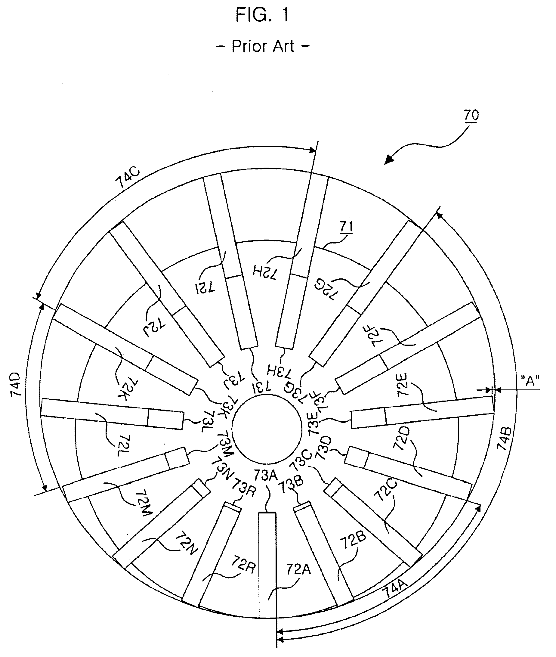
However, since the rotary scroll has a complicated structure, the scroll compressor is difficult to manufacture.

Method used


Image

  • Compressor
  • Compressor
  • Compressor

Examples


Embodiment Construction

Now, preferred embodiments of the present invention will be described in detail with reference to the accompanying drawings.

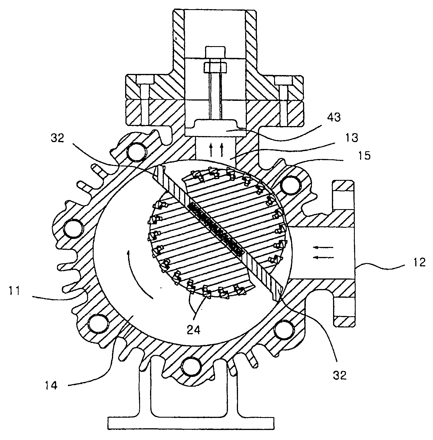
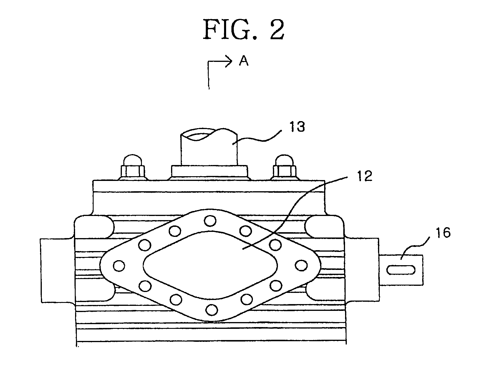
In accordance with the present invention, as shown in FIG. 2, a main body 11 of a compressor is formed as a cylinder. An inlet 12 and an outlet 13 being almost perpendicular to the inlet 12 are formed on the outer surface of the main body 11. A compression chamber 14 formed as a cylinder for connecting the inlet 12 to the outlet 13 is formed in the main body 11, and a rotary axis 16 with both ends connected to opposite ends of the main body 11 is installed within the main body 11 so as to be eccentric with the compression chamber 14.

Hereinafter, with reference to FIG. 3, the compressor of the present invention will be described in more detail. The compressor comprises the cylinder-shaped compression chamber 14, a rotor 21, and a rotary pressing member 32. The compression chamber 14 compresses the introduced medium under a sealed condition and extrudes the compr...


PUM


Abstract

The present invention relates to a compressor, and more particularly, to a compressor for continuously extruding and feeding a compressing medium introduced into a compressing chamber, by means of a pressing pin member being elastically contacted with an inner circumference surface of the compressing chamber and a rotary pressing member having two wings at left and right.

Description

TECHNICAL FIELDThe present invention relates to a compressor, and more particularly to a compressor for continuously extruding and feeding a medium introduced into a compression chamber by means of a plurality of pressing pin members elastically contacting an inner circumference of the compression chamber and a rotary pressing member having two wings on both sides.BACKGROUND ARTGenerally, compressors are divided into compressors for compressing compressible fluids such as air, gas, refrigerant, etc., and hydraulic compressors for compressing and feeding incompressible fluids such as oil, water, etc., according to media to be compressed. Further, the compressors are variously divided into piston compressors, screw compressors, centrifugal compressors, scroll compressors, and so on, according to compression methods.For example, the piston compressor conventionally compresses air, etc. by a reciprocating movement of a piston so as to generate a rotary force delivered to an engine or a ...

Claims


Application Information

Patent Timeline
Patent Type & Authority Patents(United States)
IPC IPC(8): F01C21/00F01C21/08F04C18/34F04C18/344F04C27/00
CPCF01C21/0809F04C27/002F04C18/3441F04C18/344
Inventor MAENG, HYUK-JAE
Owner MAENG HYUK JAE
Learn More