Discharge electrode and photocatalysis apparatus

a discharge electrode and photocatalysis technology, applied in the direction of physical/chemical process catalysts, disinfection, separation processes, etc., can solve the problems of closed spaces, environmental pollution, and related art, and achieve the effect of effective and stably discharge, efficiently and stably removing hazardous substances

Inactive Publication Date: 2005-03-15
KK TOSHIBA
View PDF3 Cites 28 Cited by
  • Summary
  • Abstract
  • Description
  • Claims
  • Application Information

AI Technical Summary

Benefits of technology

To solve these problems, the present invention provides a photocatalysis apparatus employing three-dimensional discharge electrodes that effectively and stably discharge and a photocatalyst that is activated by light generated by discharge of the discharge electrodes and efficiently and stably removes hazardous substances.

Problems solved by technology

It is well known that hazardous substances such as dioxins and NOx contained in the atmosphere or water cause environmental pollutions.
There are hazardous substances that cause problems in closed spaces, such as putrid gas like ethylene gas in refrigerators, sick-house-syndrome causing chemicals like formaldehyde, toluene, xylene, and aradichlorobenzene in houses, and tobacco fumes in rooms or cabins.
This related art has some problems.
Then, the photocatalyst 103 will unevenly be activated to provide insufficient catalytic performance.
The thin-film electrodes 104 are unstable when installed.
The electrodes 104 made of thin films easily shift, deform, or break if installed improperly or if exposed to excessive conditions such as a high flow rate of hazardous substances or a large amount of dust.

Method used


Image

  • Discharge electrode and photocatalysis apparatus
  • Discharge electrode and photocatalysis apparatus
  • Discharge electrode and photocatalysis apparatus

Examples


first embodiment

(First Embodiment)

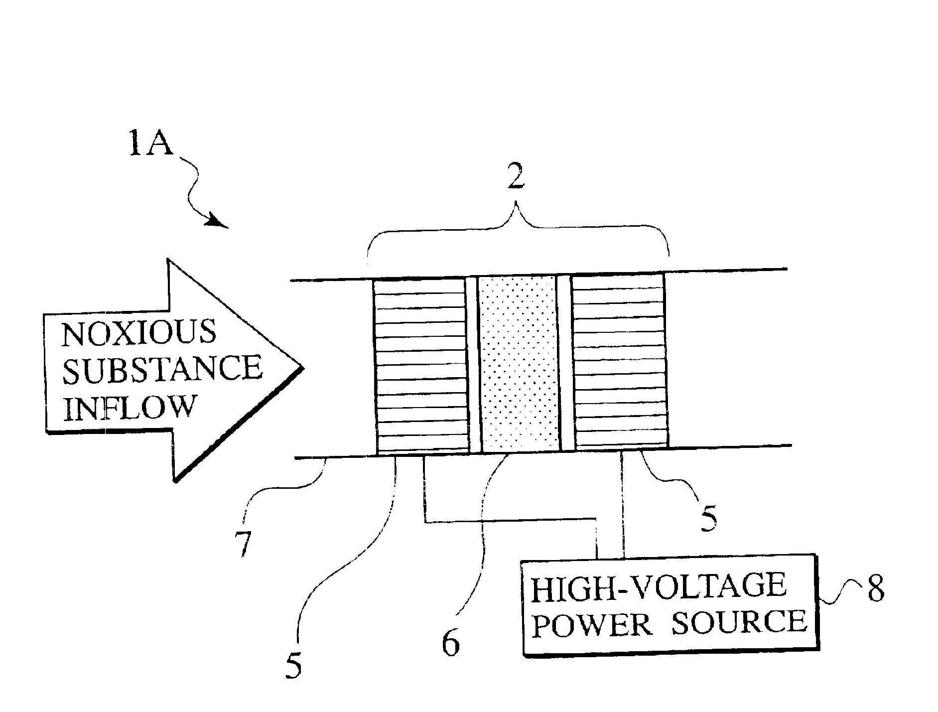
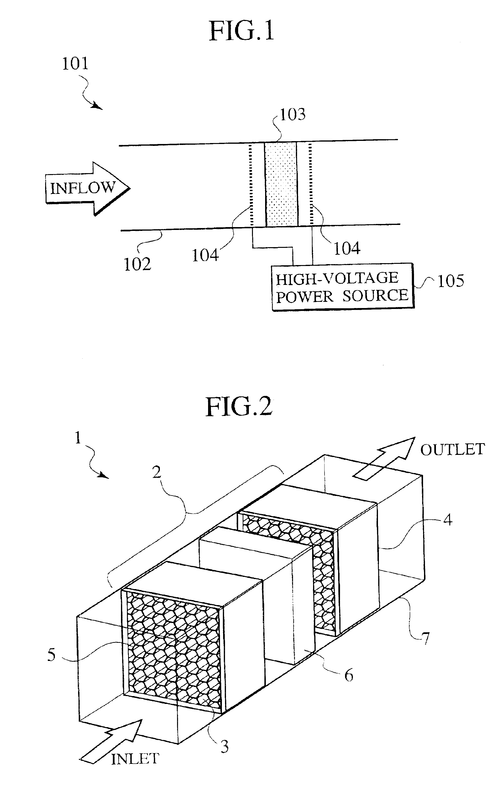
FIGS. 2 and 3 show a photocatalysis apparatus according to the first embodiment of the present invention.

In FIG. 2, the photocatalysis apparatus 1 (1A in FIG. 3) has a unit structure 2 and a casing 7 housing the unit structure 2. The casing 7 is in a pipe shape and has an inlet and an outlet to pass gas containing hazardous substances therethrough. The unit structure 2 includes a pair of honeycomb electrodes 5 and a photocatalyst module 6 sandwiched between the electrodes 5. The electrodes 5 are connected to a high-voltage power source 8 (FIG. 3).

Each electrode 5 is made of an electrode body 3 and a conductive frame 4. The electrode body 3 is a three-dimensional structure formed from cells made of a conductive foil. The electrode body 3 has front, back, and side faces in which the front and back faces are separated from each other by a predetermined distance and have a honeycomb shape, to pass gas containing hazardous substances through the electrode body 3. The si...

second embodiment

(Second Embodiment)

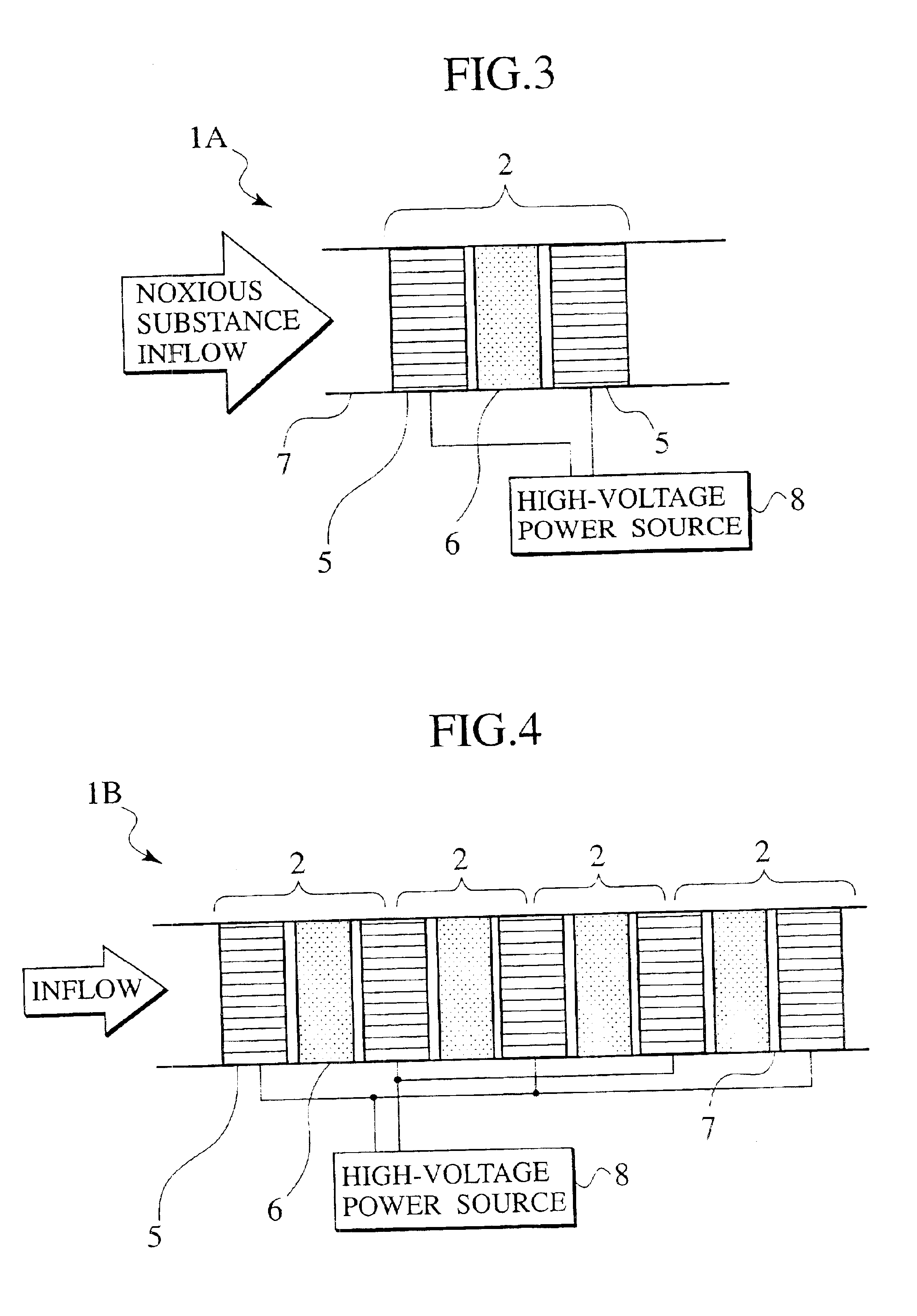
FIG. 4 shows a photocatalysis apparatus 1B according to the second embodiment of the present invention. The second embodiment employs a plurality of unit structures each being the unit structure 2 of FIGS. 2 and 3.

The photocatalysis apparatus 1B has a plurality of (four in this example) unit structures 2, a casing 7 accommodating the unit structures 2, and a high-voltage power source 8. Each unit structure 2 has a pair of honeycomb electrodes 5 and a photocatalyst module 6 sandwiched between the electrodes 5. The electrodes 5 are connected to the power source 8.

Two adjacent unit structures 2 share one electrode 5 so that each electrode 5 may efficiently emit light toward the unit structures 2.

The configuration, material, etc., of the electrode 5, photocatalyst module 6, semiconductor catalytic particles of the module 6, and power source 8 are basically the same as those of the first embodiment, and therefore, are not explained again.

Operation of the photocatalysis...

third embodiment

(Third Embodiment)

FIG. 5 shows a photocatalysis apparatus 1C according to the third embodiment of the present invention. The third embodiment is a combination of the photocatalysis apparatus of the first embodiment and an ozonolysis catalyst 9.

The photocatalysis apparatus 1C has a unit structure 2, the ozonolysis catalyst 9, a casing 7 housing the unit structure 2 and ozonolysis catalyst 9, and a high-voltage power source 8.

The unit structure 2 includes a pair of honeycomb electrodes 5 and a photocatalyst module 6 sandwiched between the electrodes 5. The electrodes 5 are connected to the power source 8. The ozonolysis catalyst 9 is arranged downstream from the unit structure 2 in a gas flowing direction.

The configuration, material, etc., of the electrode 5, photocatalyst module 6, semiconductor catalytic particles of the module 6, and power source 8 are basically the same as those of the first embodiment, and therefore, are not explained again.

According to the first and second embod...


PUM

PropertyMeasurementUnit
thicknessaaaaaaaaaa
thicknessaaaaaaaaaa
frequencyaaaaaaaaaa

Abstract

A photocatalysis apparatus has at least one unit structure (2). The unit structure has a photocatalyst module (6) and a pair of discharge electrodes (5) sandwiching the photocatalyst module. The photocatalyst module includes a photocatalyst and a three-dimensional ceramic mesh base carrying the photocatalyst. At least one of the discharge electrodes is a three-dimensional discharge electrode having an electrode body (3) and a conductive frame (4). The electrode body consists of cells made of a conductive foil and has front, back, and side faces. The front and back faces are separated from each other by a predetermined distance and have a shape selected from a group including a honeycomb, a lattice, and a mesh. The side faces of the electrode body is covered with the conductive frame.

Description

CROSS REFERENCE TO RELATED APPLICATIONSThis application is based upon and claims the benefit of priority from the prior Japanese Patent Application No. 2001-148427 filed on May 17, 2001, the entire contents of which are incorporated herein by reference.BACKGROUND OF THE INVENTION1. Field of the InventionThe present invention relates to a three-dimensional discharge electrode that effectively and stably discharges, and to a photocatalysis apparatus employing the three-dimensional discharge electrode and a photocatalyst that becomes active when irradiated with light (ultraviolet rays) emitted from the electrode and removes hazardous substances.2. Description of the Related ArtIt is well known that hazardous substances such as dioxins and NOx contained in the atmosphere or water cause environmental pollutions. To effectively remove the hazardous substances, various studies have energetically been made. There are hazardous substances that cause problems in closed spaces, such as putrid ...

Claims


Application Information

Patent Timeline
Patent Type & Authority Patents(United States)
IPC IPC(8): B01D53/32B01D53/88B03C3/00B03C3/016B03C3/40B03C3/41B01J35/00B01J35/04A61L9/00A61L9/20B01D53/86B01J19/00B01J19/08B01J35/02
CPCB01D53/32B01D53/885B03C3/016B03C3/41B01D2255/802B01D2257/106Y02C20/10B01J35/04B01J35/004B01D53/86
Inventor SEGAWA, NOBORUUCHIDA, YUTAKAIMAMURA, TAKESHISHIMURA, NAOHIKO
Owner KK TOSHIBA
Why Eureka
Try Eureka