Method of generating hydrogen from borohydrides and water

a technology of borohydride and hydrogen, applied in the direction of electric generators, transportation and packaging, rotary stirring mixers, etc., can solve the problems of high pressure, heavy vessels, difficulty in storage, etc., and achieve the effect of convenient and compact storage or packing

Inactive Publication Date: 2005-03-15
GM GLOBAL TECH OPERATIONS LLC
View PDF1 Cites 14 Cited by
  • Summary
  • Abstract
  • Description
  • Claims
  • Application Information

AI Technical Summary

Benefits of technology

Thus, the two augers provide a tri-functional mixing / grinding / conveying purpose. First, the mixing elements are used to expose by-product coated borohydride particles to water. Second, the mixing elements crush foamy or porous by-product agglomerations into manageable particles, preferably a powder. As a powder, by-product waste can be easily and compactly stored, or packed, in a lower volume byproducts storage vessel. Third, the mixing elements operate as a two-phase mass handling device that transports solid and liquid materials axially through the reactor. The flow of the generated hydrogen and gravity (in the case of the inclined or vertical reactor) also assist in conveying all reaction products through and out of the axial flow reactor vessel.

Problems solved by technology

However, the problem of using hydrogen as a power source is its difficulty to store, especially in on-off mobile applications.
These vessels are heavy, and high pressure is a concern.
Metal hydrides, MHx, contain thermally releasable hydrogen, but only in small, inefficient amounts.
But this approach, too, is an engineering challenge.
This practice impedes further reaction of water with unreacted hydride.
The Kerrebrock, et al process is not useful in applications like automotive vehicles requiring go and stop operation.

Method used


Image

  • Method of generating hydrogen from borohydrides and water
  • Method of generating hydrogen from borohydrides and water

Examples


Embodiment Construction

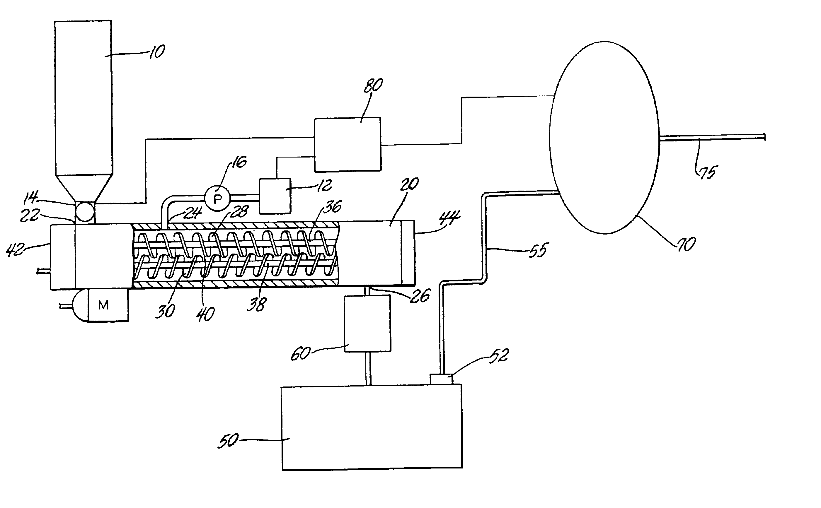
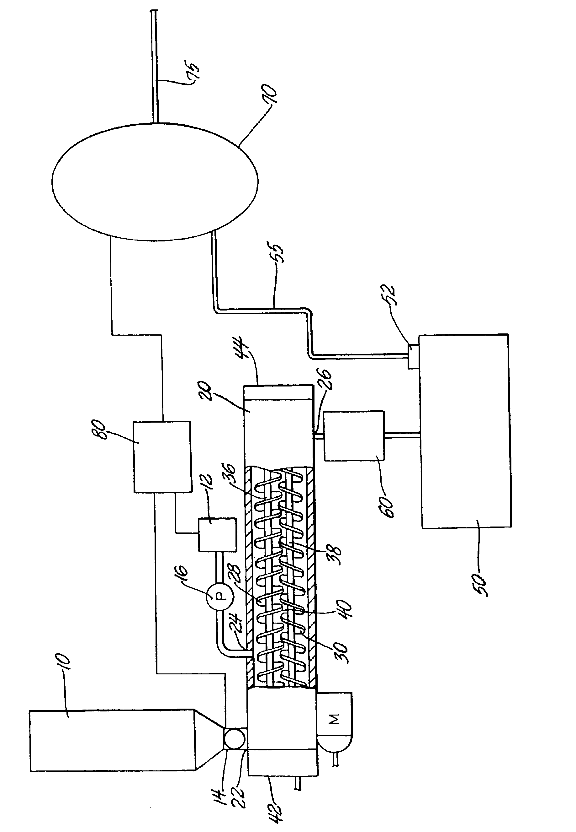
A method is provided that generates hydrogen to power a hydrogen consuming device, e.g., a fuel cell. Hydrogen is stored on-board a motorized vehicle in the form of dry lithium borohydride and / or sodium borohydride pellets of essentially uniform size and mass, or in the form of a powder. Lithium borohydride is preferred for use in the method of this invention because it has the highest mass of hydrogen for a given mass of hydride, and is the lightest borohydride available. Furthermore, it generates substantial heat upon hydrolysis reducing the requirement for a supplemental heat source.

Hydrogen is generated by hydrolyzing the borohydride using a stoichiometrically balanced (i.e., substantially chemically balanced) amounts of borohydride and water. More specifically, the optimal yield of hydrogen gas is generated by maintaining a 1.6 to 2.5 parts by mass of water per 1 part of lithium borohydride mixture, or 1 to 1.5 parts by mass of water per 1 part of sodium borohydride mixture. Up...


PUM

PropertyMeasurementUnit
temperatureaaaaaaaaaa
temperaturesaaaaaaaaaa
temperatureaaaaaaaaaa

Abstract

A method is provided that generates hydrogen to power a hydrogen consuming device. Hydrogen is stored on-board a vehicle in dry lithium and/or sodium borohydride particles. Upon demand from the hydrogen consuming device, such as a fuel cell, a portion of the borohydride is conveyed to an axial flow reactor. Water is then injected into the reactor in controlled amounts to hydrolyze the borohydride particles thus, producing hydrogen gas and solid-phase by-products. The reactor includes parallel, closely spanned, counter rotating augers to mix and convey the borohydride particles and solid by-products through the reactor. A separate grinding mechanism can be used to further crush and grind large by-product particles to increase packing efficiencies in a by-products storage vessel, where reaction products will later be stored. Hydrogen gas produced in the reaction is delivered to either a hydrogen buffer container for temporary storage or to the hydrogen consuming device.

Description

TECHNICAL FIELDThis invention relates to hydrogen generation systems and more specifically, to a process of generating hydrogen by hydrolyzing dry borohydride particles separately stored from water.BACKGROUND OF THE INVENTIONIn place of hydrocarbons as a source of energy to generate power, hydrogen has been suggested as being a more beneficial alternative. Hydrogen gas can generate more power per gram and emit less, or even no, exhaust pollutants into the atmosphere. However, the problem of using hydrogen as a power source is its difficulty to store, especially in on-off mobile applications.Hydrogen gas can be stored at high pressures in thick walled vessels on-board a motorized vehicle. These vessels are heavy, and high pressure is a concern. Metal hydrides, MHx, contain thermally releasable hydrogen, but only in small, inefficient amounts. Lithium and sodium borohydrides contain a higher proportion of hydrogen that can be released by hydrolysis. But this approach, too, is an engin...

Claims


Application Information

Patent Timeline
Patent Type & Authority Patents(United States)
IPC IPC(8): B01J7/00B01J7/02B01J8/10B01J8/08B01F7/02B01F7/08C01B3/00C01B3/06H01M8/06
CPCB01F7/082B01J7/02B01J8/10H01M8/065C01B3/065B01J2219/182Y02E60/50H01M8/04216Y02E60/362Y02E60/36B01F27/722
Inventor JORGENSEN, SCOTT WILLIS
Owner GM GLOBAL TECH OPERATIONS LLC
Why Eureka
Try Eureka