Method and apparatus for reducing dynamo-electric machine vibration

a technology of dynamo-electric machines and vibration reduction, which is applied in the direction of dynamo-electric machines, electromagnets, cores/yokes, etc., can solve the problems of rotor unbalance problems, magnitude and angle of vibration changes noticeably, and bars locking in their own

Inactive Publication Date: 2005-03-15
GENERAL ELECTRIC CANADA INC A CO OF CANADA
View PDF25 Cites 15 Cited by
  • Summary
  • Abstract
  • Description
  • Claims
  • Application Information

AI Technical Summary

Problems solved by technology

Such reaction forces are proportional to slot frictional forces, which oppose rotor bar expansion and may cause rotor unbalance problems.
In some motors, the magnitude and angle of the vibration changes noticeably with rotor temperature because of non-uniform expansion of the rotor.
Such non-uniform expansion may result from some rotor bars locking in their slots when the slot frictional force exceeds the thermal elongation differential between bar and slot.

Method used


Image

  • Method and apparatus for reducing dynamo-electric machine vibration
  • Method and apparatus for reducing dynamo-electric machine vibration
  • Method and apparatus for reducing dynamo-electric machine vibration

Examples


Embodiment Construction

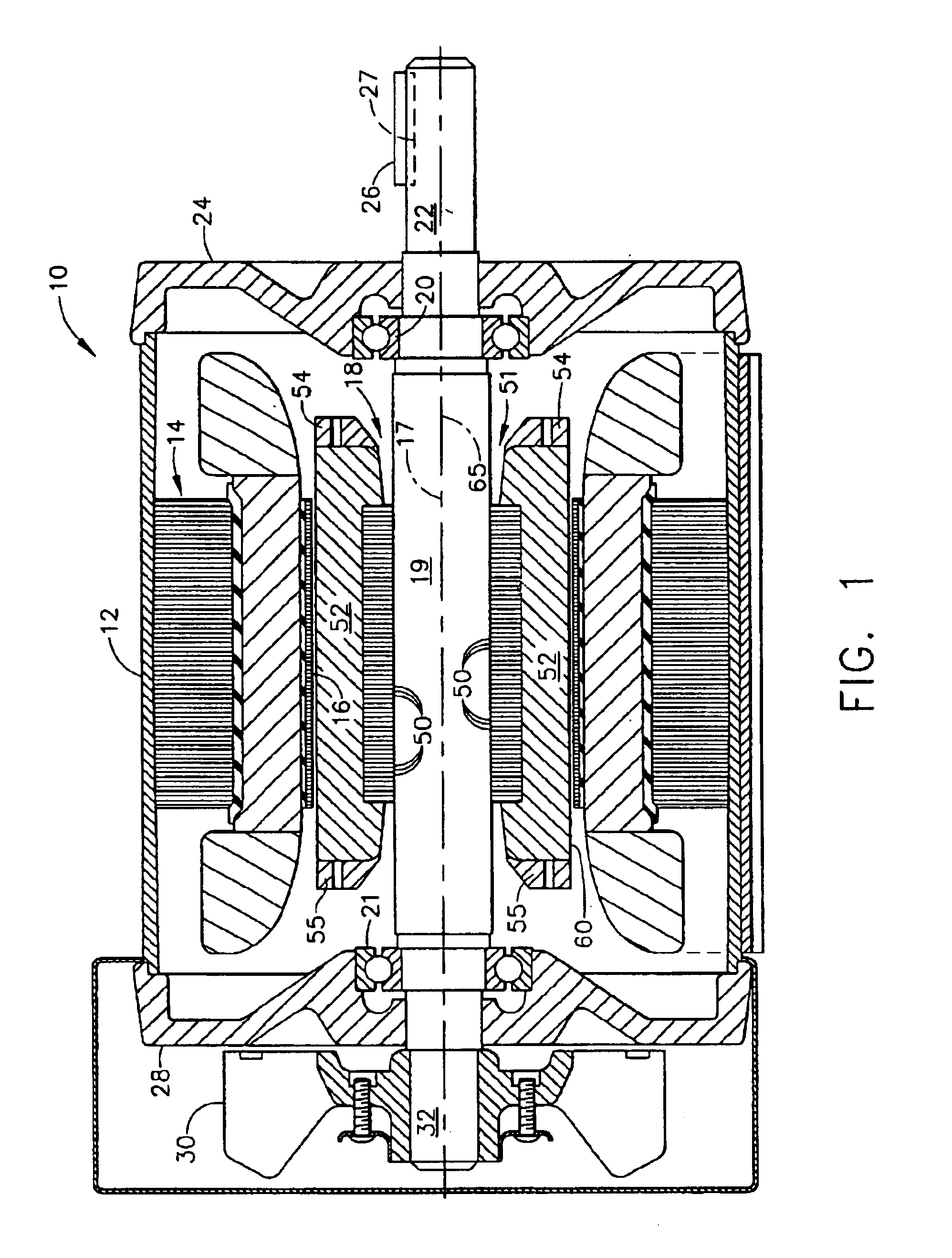
FIG. 1 illustrates a side cross sectional view of an electric motor 10. Motor 10 includes a substantially cylindrical outer casing 12, and a generally cylindrical stator 14 that is positioned substantially coaxially within outer casing 12, and includes a coaxial stator bore 16 that extends therethrough. A rotor 18 includes a shaft 19 and is supported by a front bearing 20 and a back bearing 21 which are each coupled to casing 12. Rotor 18 extends axially through stator bore 16 for rotational movement about a stator bore axis 17. In an exemplary embodiment, a rotor shaft extension 22 extends axially from a front end shield 24 of motor 10, and includes a key 26 that projects radially outward from a keyway 27 that is cut axially a distance from shaft extension 22. Key 26 locks shaft extension 22 into a corresponding key way cut in a load member (not shown) e.g. a fan, to which rotational motive power is to be supplied by motor 10.

A back end shield 28 together with casing 12 and front e...


PUM

PropertyMeasurementUnit
conductiveaaaaaaaaaa
resiliently flexibleaaaaaaaaaa
distanceaaaaaaaaaa

Abstract

A method of fabricating a dynamo-electric machine rotor is provided. The method includes forming a plurality of laminations, such that a plurality of openings extend through the laminations between an outer peripheral edge and an inner peripheral edge arcuately spaced about the lamination wherein each opening includes an edge with a tongue that extends into the opening, stacking the laminations to form a core wherein adjacent opening are substantially aligned to form a slot in the core and filling the core slots with rotor bar material.

Description

BACKGROUND OF INVENTIONThis invention relates generally to dynamo-electric machines and, more particularly, to structures for reducing vibration within the dynamo-electric machine.Dynamo-electric machine rotors formed of a stack of laminations having slots equally spaced from one another about the periphery of each lamination are known. Such rotors are often used in inductive AC motors and generators and include conducting members that extend axially along the rotor through aligned slots of the stacked laminations. The conducting members or bars interact with a rotating magnetic field created in an air gap between the outer circumference of the rotor and the inner circumference of the machine stator. Windings embedded in slots between radially inwardly projecting teeth of the stator, adjacent the air gap, are connected to the AC mains, and the stator winding conductors pass through a certain order of the stator slots so as to cause magnetic flux in the air gap to rotate in synchroni...

Claims


Application Information

Patent Timeline
Patent Type & Authority Patents(United States)
IPC IPC(8): H02K3/48H02K1/22H02K1/26H02K17/16
CPCH02K1/265H02K3/48H02K17/165Y10T29/49078Y10T29/49012
Inventor MOORE, BRADLEY GRAHAM
Owner GENERAL ELECTRIC CANADA INC A CO OF CANADA
Why Eureka
Try Eureka