Electro-mechanical lock assembly

a technology of electronic components and locking assemblies, applied in the direction of wing knobs, programme control, instruments, etc., can solve the problems of increasing the number the limited placement of most locking assemblies, and the attractive target of thieves and vandals, so as to improve the security of the enclosure and improve the accuracy of tracking business activity.

Inactive Publication Date: 2005-03-15
STAR LOCK SYST
View PDF48 Cites 147 Cited by
  • Summary
  • Abstract
  • Description
  • Claims
  • Application Information

AI Technical Summary

Benefits of technology

Briefly described, the present invention generally comprises an electro-mechanical lock assembly or system for securing a door or other closure device for enclosures such as vending machines, trailers, etc. The electro-mechanical locking apparatus of the present invention is designed to provide enhanced security for the enclosure and to additionally provide for data collection and transfer of information to enable more accurate tracking business activity. Typically, the enclosure to which the electro mechanical lock assembly of the present invention is applied will include an enclosure frame and at least one door hingedly attached to the enclosure frame so as to be movable between an unlocked, open position displaced from the enclosure frame and a closed, locked position secured against the enclosure frame.
The electro-mechanical lock assembly generally includes a T-handle having a mechanical lock and an electronic lock control system. The mechanical lock secures the T-handle in a T-handle housing and prevents the rotation of the locking post. A T-handle lock bolt is disengaged or actuated remotely through the electronic lock control system.

Problems solved by technology

Such an unlocking or opening operation generally is a substantially manual operation such that most locking assemblies generally are limited in their placement to regions or areas where they can be readily reached and operated, i.e., in the middle of the door.
Such easy access to these locking assemblies, however, tends to make these locking assemblies easy targets for vandals or thieves that can shield their actions from view while attacking the security of the enclosure by picking or smashing the lock to remove the primary and sometimes only point of security between the door and the frame of the enclosure.
In particular, vending machines have become an increasingly favorite target of vandals and thieves.
The increased popularity and increased capacity of vending machines as well as the expansion of products to higher priced items have significantly increased the amounts of money taken in by vending machines, providing an increasingly attractive target to thieves and vandals.
Such re-keying is typically burdensome and very costly, especially where there are a significant number of locks that need to be re-keyed.

Method used


Image

  • Electro-mechanical lock assembly
  • Electro-mechanical lock assembly
  • Electro-mechanical lock assembly

Examples


first embodiment

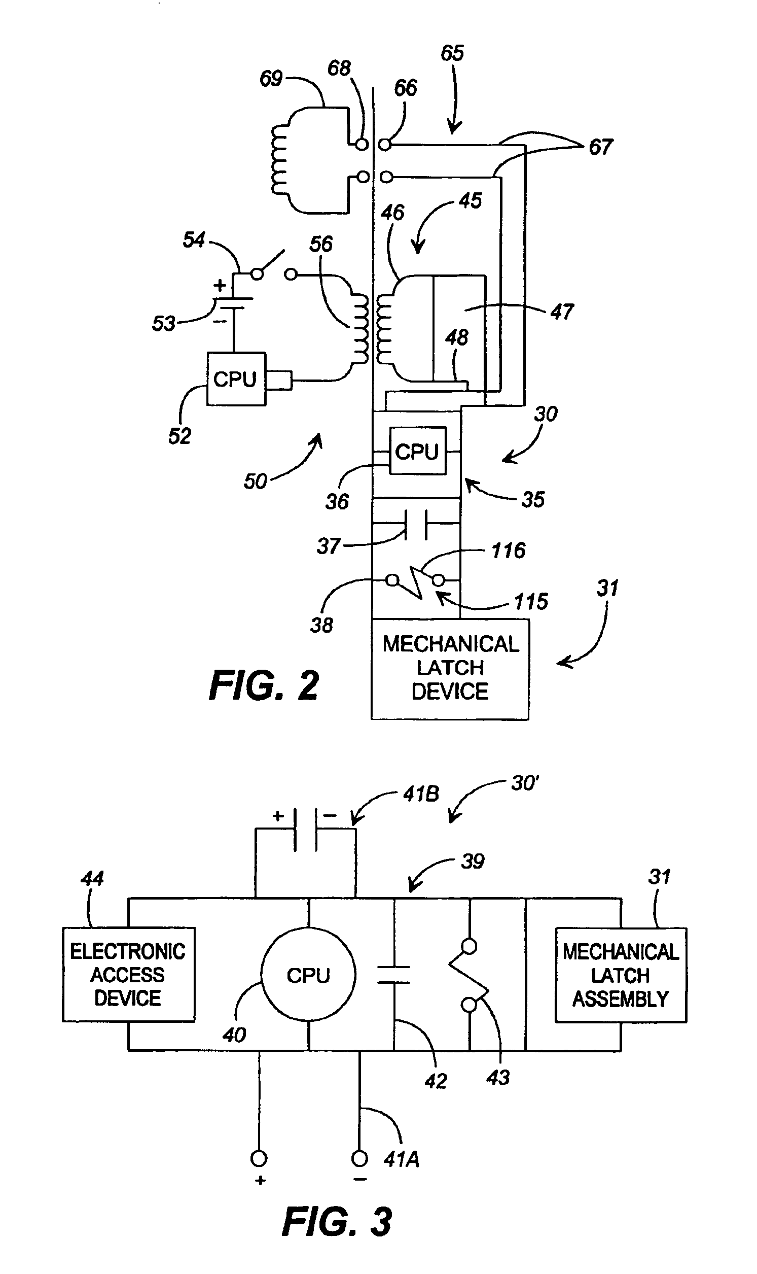
A key controller or data transmitter 50 is provided for inductively transmitting power and control instructions or signals through the door(s) of the enclosure to the lock controller via the data / power link and for receiving data and operational information from the lock controller. In a first embodiment, shown in FIG. 4A, the key controller 50 typically is a hand held unit which includes a housing 51, a processor chip 52 such as a 16 to 128 bit microprocessor, a power source 53 such as a 9-12 volt battery that typically is rechargable or which enables a connection to an AC outlet or other external power source, a switch 54, and an inductive coupling or link 56 that matches the inductive coupling of the data / power link. For example, if the data / power link includes a ferrite coil inductive coupling 46, the key controller typically will include a matching ferrite coil. The key controller is aligned with the data / power link and transmits power inductively through the front panel of the...

embodiment 70

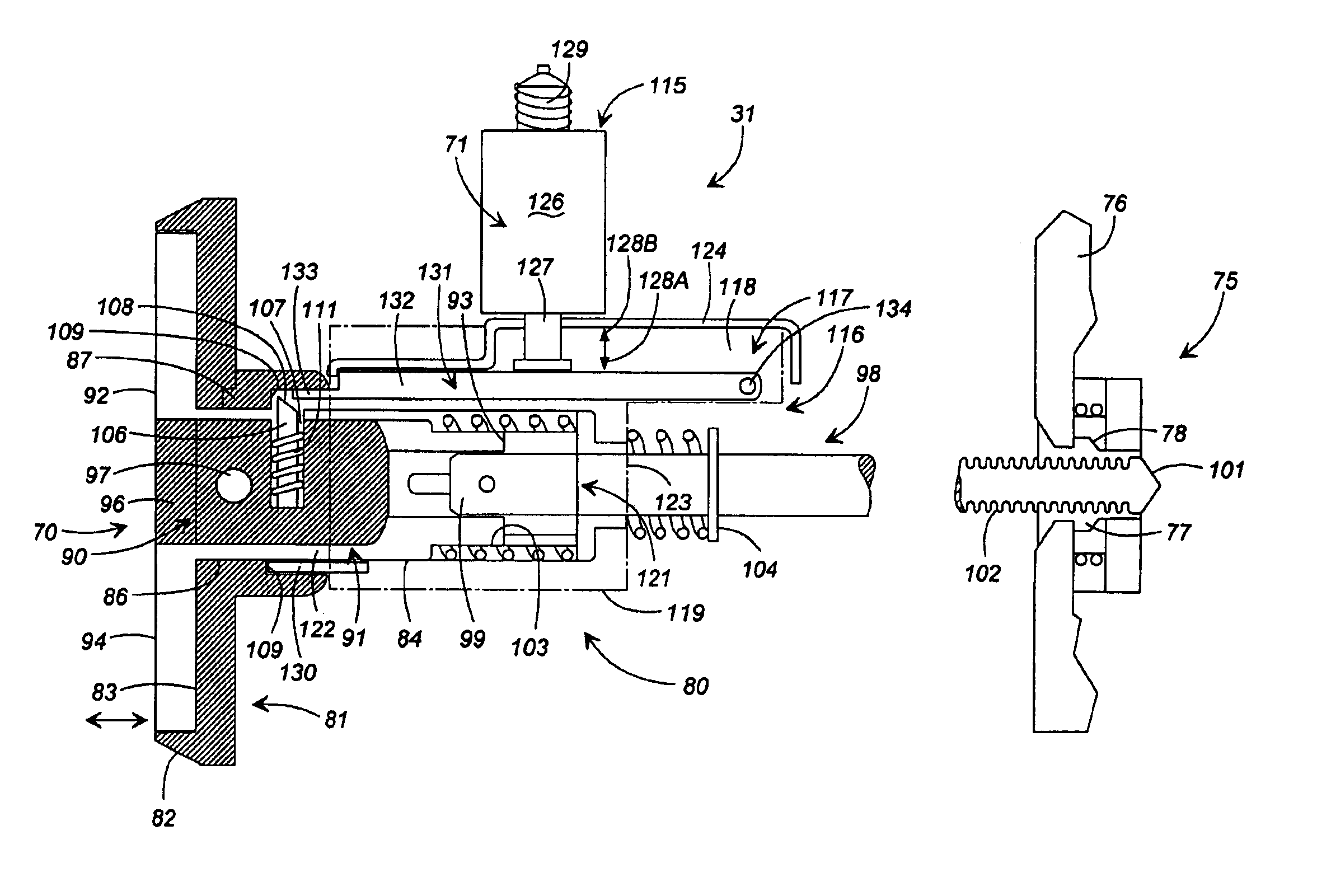
A third embodiment of the release mechanism 71″ for use in an additional embodiment 70″ of the T-handle assembly is illustrated in FIG. 6C. In this embodiment, the release mechanism 71″ includes an actuator 150, such as a 12 to 24 volt approximately 1.0 ohm resistance solenoid 151 mounted above the T-handle assembly as shown in FIG. 6C. The actuator 150 is mounted on a support saddle 152 (shown in phantom lines) having a removable gauging element releasibly mounted thereto. The solenoid 151 generally includes a plunger 153 having a distal end 154 displaced from the solenoid, and which is received and held within a mounting block 156. A tension spring 157 is positioned about the plunger 153 and is secured at one end within the mounting block 156. A release element 158 is slidably mounted on the plunger so as to be movable in the direction of arrows 159A and 159B upon actuation and movement of the solenoid in the direction of arrows 159A and 159B.

The release element generally includes...


PUM


Abstract

An electro-mechanical lock release assembly for an enclosure such as a vending machine and including an electronic lock controller for disengaging a lock assembly securing the door of the enclosure against the enclosure frame in a closed, locked position. The lock controller is actuated remotely through a key controller to disengage the lock assembly and enable the door of the enclosure to be moved to an open position for accessing the enclosure.

Description

BACKGROUND OF THE INVENTIONLocking devices commonly are used to hold lids, doors or other closure elements of boxes, cabinets, doorways and other framed structures in closed and / or locked positions, and further typically are used to provide some measure of security against unauthorized or inadvertent access. For example, conventional vending machines generally include a key operated T-handle locking device that typically includes a locking assembly and a post mounted to the frame and door of the vending machine so that the door of the vending machine is locked when moved into a closed position against the machine frame by the insertion of the post into the retention element in a bracket assembly. Such locking assemblies further typically include a housing that defines an axial passage in which the post is attached to and / or operating in conjunction with a T-handle, is received and is engaged by a retention element that engages the surface of the post. The retention element grips the...

Claims


Application Information

Patent Timeline
Patent Type & Authority Patents(United States)
IPC IPC(8): E05B47/06E05B5/02E05B5/00G07F9/10E05B1/00
CPCE05B5/003G07F9/10E05B47/0657E05B1/0092E05B47/0004E05B15/1614Y10T70/7062Y10T292/699Y10T292/702
Inventor STILLWAGON, WOODROW C.
Owner STAR LOCK SYST
Why Eureka
Try Eureka