Spatial position determination system

Inactive Publication Date: 2005-03-15
WI LAN INC
View PDF22 Cites 58 Cited by
  • Summary
  • Abstract
  • Description
  • Claims
  • Application Information

AI Technical Summary

Benefits of technology

[0006]A spatial position determination system according to various aspects of the present invention determines a spatial position of a tracker device relative to an object send

Problems solved by technology

Measurement of azimuthal angle to a given object tends to be less accurate than measurement of distance to that object.
Slight frequency deviations in the forward and return signals can cause significant phase d

Method used


Image

  • Spatial position determination system
  • Spatial position determination system
  • Spatial position determination system

Examples


example a

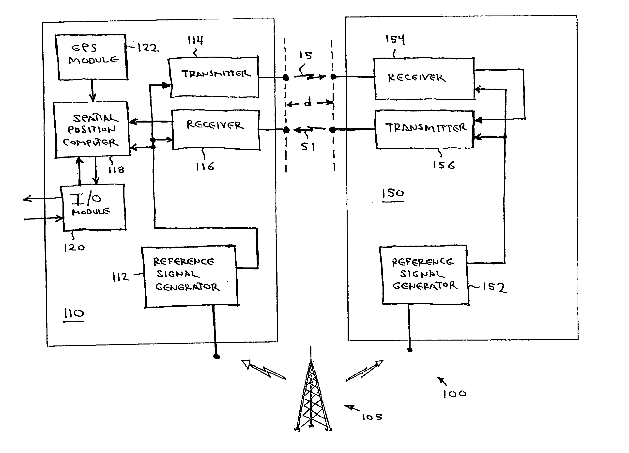
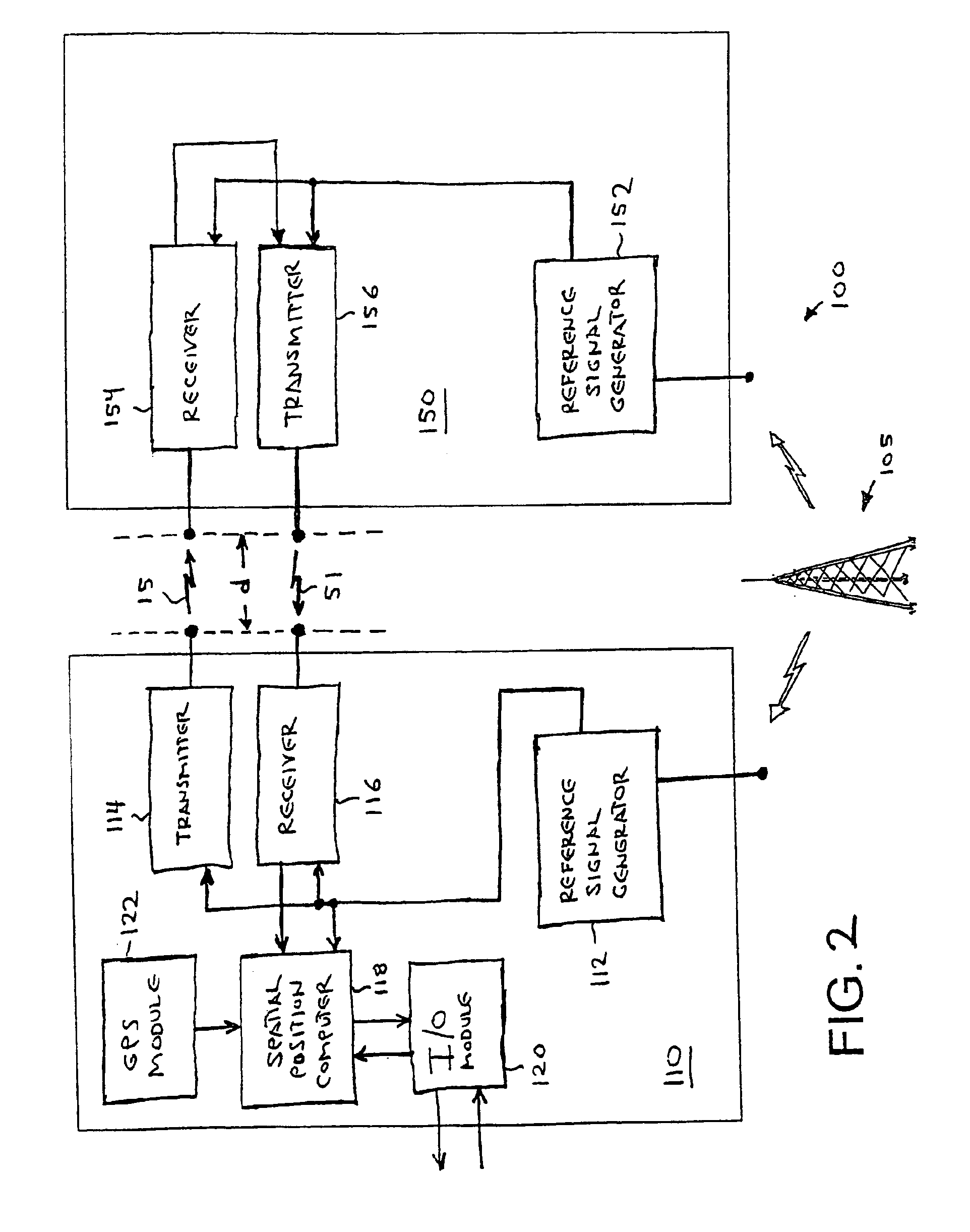
[0114]Instead of transmitting an unmodulated carrier as described above, tracker 110 can transmit a carrier phase modulated by a pseudo-random sequence. The chip time (i.e., duration of each phase modulation symbol) can be determined by the time base shared by the tracker and the target. The chip rate can be a predetermined fraction of the carrier frequency, or a predetermined fraction of the broadcasted signal's frequency.

[0115]Transponder 150 performs a correlation maximization search to determine the start time of the pseudo-random sequence. This correlation needs to be performed only during the initial synchronization acquisition process. All subsequent transmissions can remain synchronized due to the common time base.

[0116]In this variation, system 100 relies on the ability of both tracker 110 and transponder 150 to measure the phase of the signals they each receive. The DSSS phase modulation does not interfere with this measurement. In each DSSS receiver the incoming signal is...

example b

[0118]In some implementations, it may be desirable to phase stabilize to an FM broadcast station. However, FM signals do not have constant phase. Variations of tracker 110 and transponder 150 may overcome this issue by both computing an averaged reference signal in the same way. For example, each unit may compute the instantaneous broadcast frequency to be 107 divided by the time elapsed during the previous 107 cycles. Continuous computation would require a circular buffer.

example c

[0119]Phase stabilization can be to subcarriers of a broadcasted signal rather than carrier of the signal. For example, variations of reference signal generators 112 and 152 can phase stabilize other components to the color-burst frequency from TV stations, or to commercial subcarriers from FM broadcast stations.


PUM


Abstract

A system is disclosed that determines a spatial position of a tracker device relative to an object sending a return signal to the tracker. Such a system advantageously maintains phase accuracy between a forward signal from the tracker device and the return signal generator from the object. The system can include, as part of a tracker device, a reference signal generator, a transmitter, a receiver, and a spatial position computer. The reference signal generator is responsive to and phase-stabilized by a broadcast signal, e.g., a signal received from a commercial AM broadcast transmitter. The transmitter and receiver are both coupled to and phase-stabilized by the tracker reference signal generator. Variations and methods with different advantageous features are also described.

Description

BACKGROUND OF THE INVENTION[0002]The problem of determining the spatial position of objects is an ancient one. Perhaps the simplest and oldest known solution is to pace off a distance to a visible object by walking toward it along a straight path. More accurate and recent techniques include triangulating the location of a hidden object based on estimated distances or azimuthal angles to the object.[0003]Measurement of azimuthal angle to a given object tends to be less accurate than measurement of distance to that object. Extremely precise instruments have been developed for distance measurement. For example, an optical instrument disclosed in U.S. Pat. No. 5,430,537 to Liessner et al. purports to have accuracy around the 1-10 micron resolution of light wavelengths. This instrument is based on phase changes between a light beam sent to a passive reflector and another light beam returned from the reflector.[0004]Less precise instruments for phase-based distance measurement can provide...

Claims


Application Information

Patent Timeline
IPC IPC(8): G08B21/00G08B21/02G01S19/48
CPCG01S5/14G08B21/0244G01S13/878
Inventor RADIN, LON B.
Owner WI LAN INC
Why Eureka
Try Eureka