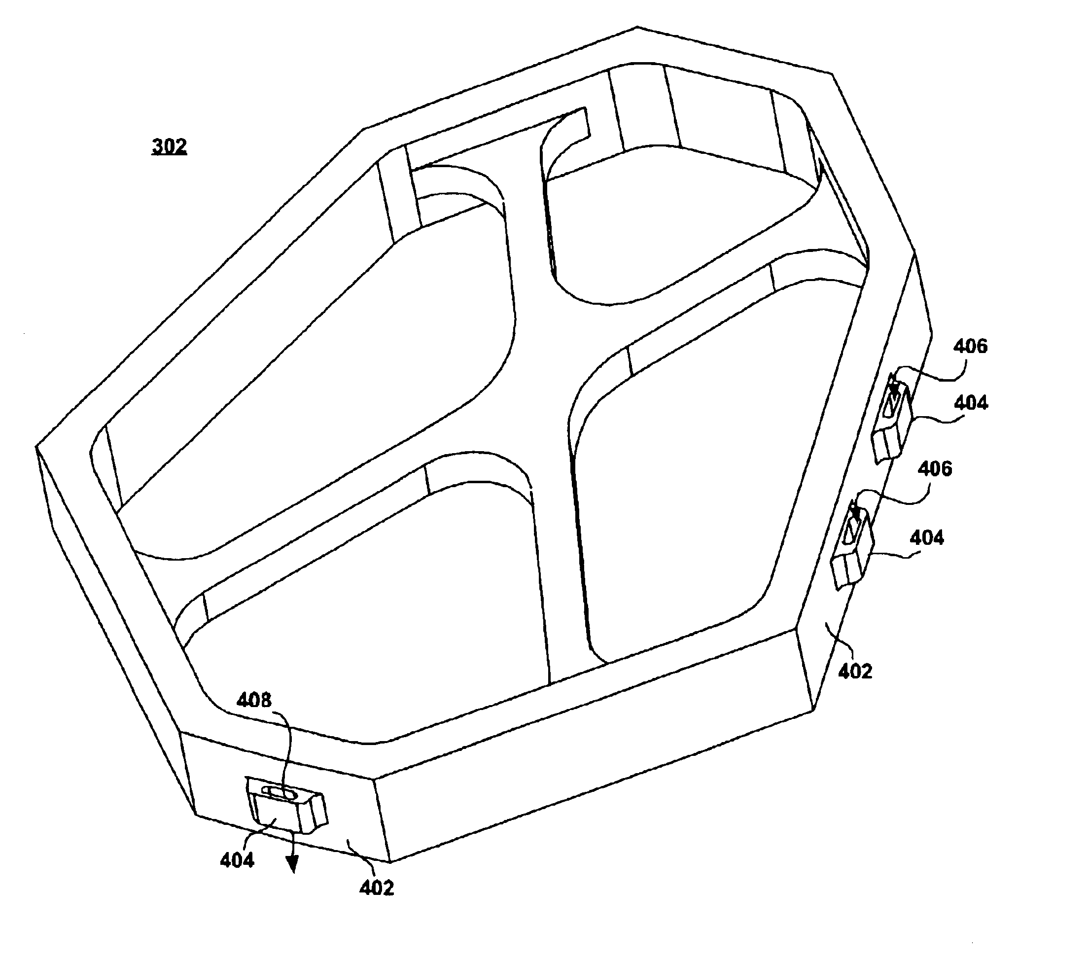
Cleating features to improve adhesive interface between a bobbin and a coil of an actuator coil portion of a hard disk drive
- Summary
- Abstract
- Description
- Claims
- Application Information
AI Technical Summary
Benefits of technology
Problems solved by technology
Method used
Image

Examples
Embodiment Construction
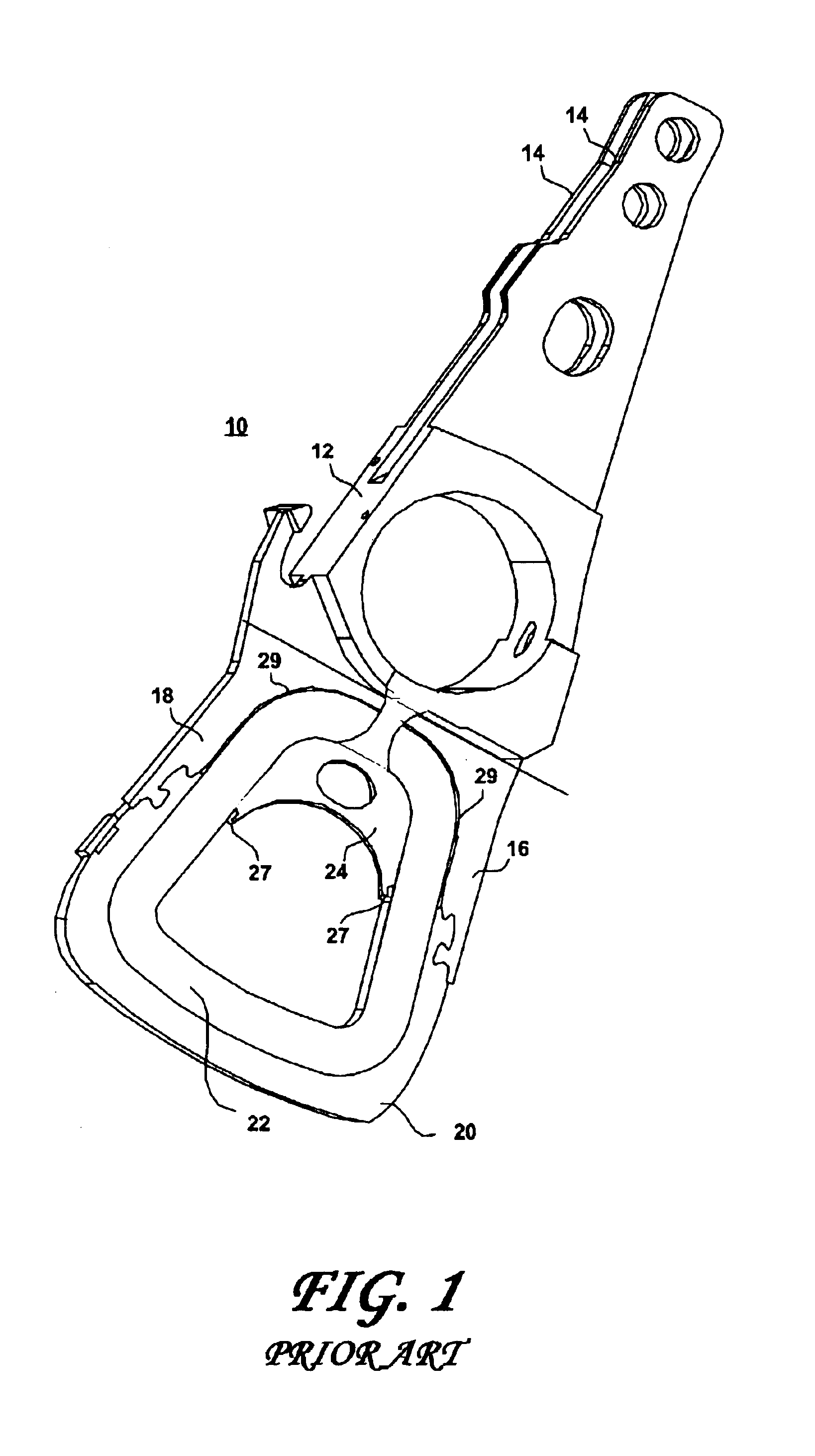
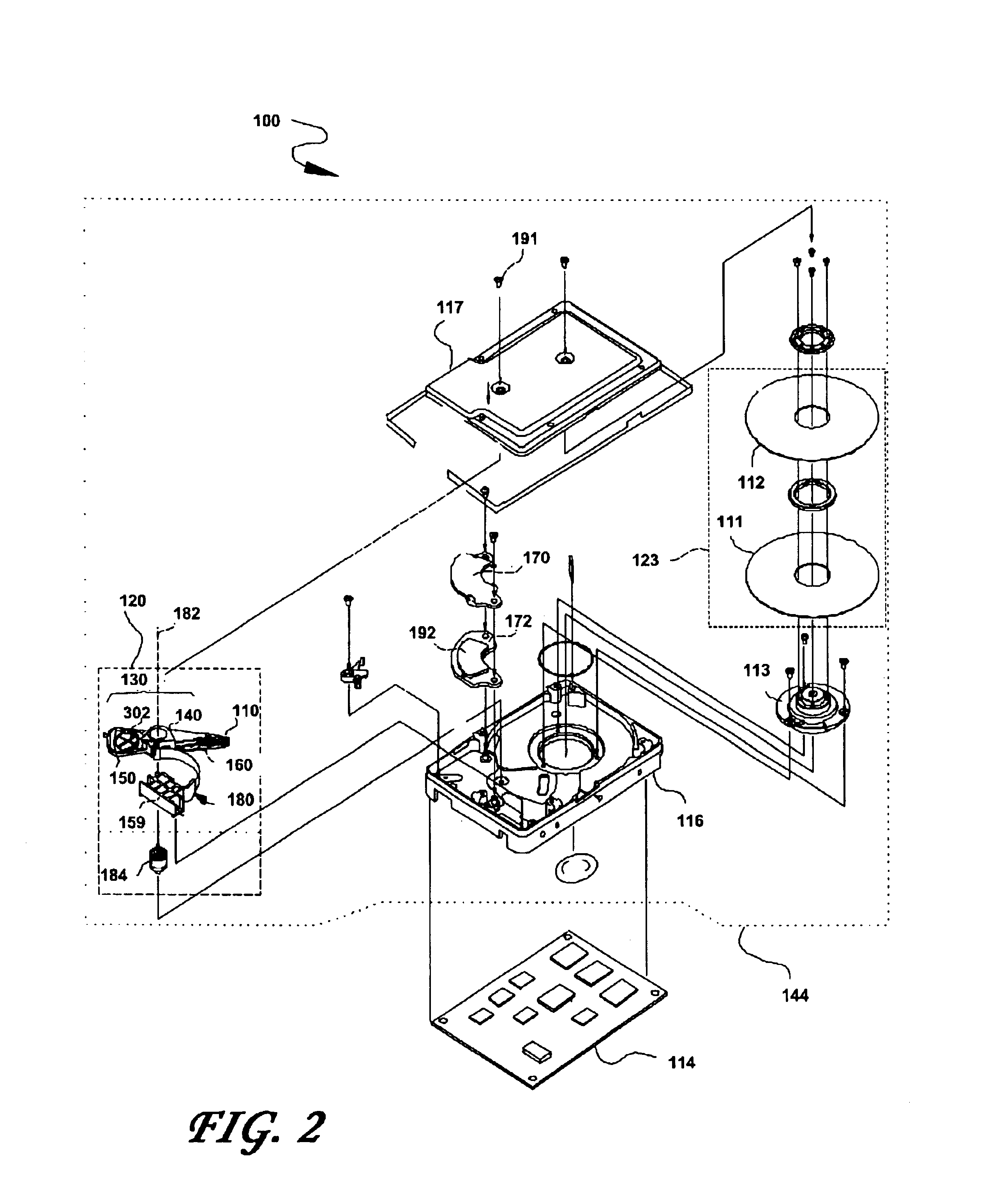
FIG. 2 shows the principal components of a magnetic disk drive 100 constructed in accordance with the present invention. With reference to FIG. 1, the disk drive 100 comprises a head disk assembly (HDA) 144 and a printed circuit board assembly (PCBA) 114. The HDA 144 includes a base 116 and a cover 117 attached to the base 116 that collectively house a disk stack 123 that includes a single magnetic disk or a plurality of magnetic disks (of which only a first disk 111 and a second disk 112 are shown), a spindle motor 113 attached to the base 116 for rotating the disk stack 123, a head stack assembly (HSA) 120, and a pivot bearing cartridge 184 that rotatably supports the HSA 120 on the base 116. The spindle motor 1113 rotates the disk stack 123 at a constant angular velocity. The HSA 120 comprises a swing-type or rotary actuator assembly 130, at least one head gimbal assembly (HGA) 110, and a flex circuit cable assembly 180. The rotary actuator assembly 130 includes a body portion 14...
PUM
 Abstract
Description
Claims
Application Information
 - Generate Ideas
- Intellectual Property
- Life Sciences
- Materials
- Tech Scout
- Unparalleled Data Quality
- Higher Quality Content
- 60% Fewer Hallucinations
Browse by: Latest US Patents, China's latest patents, Technical Efficacy Thesaurus, Application Domain, Technology Topic, Popular Technical Reports.
© 2025 PatSnap. All rights reserved.Legal|Privacy policy|Modern Slavery Act Transparency Statement|Sitemap|About US| Contact US: help@patsnap.com