
Method and apparatus for generating and transmitting a stationary dither code

a technology of stationary dithering and code generation, applied in the field of data communication and timing systems, can solve the problems of difficult for a receiver to determine its phase, require an expensive, complex and unwieldy receiver, and set the correct time of day

Inactive Publication Date: 2005-03-15
EXCELIS INC
View PDF7 Cites 6 Cited by
  • Summary
  • Abstract
  • Description
  • Claims
  • Application Information

AI Technical Summary

Benefits of technology

Yet a further object of the present invention is to use a single pseudonoise generator to generate a long code with the easier detection characteristics typical of a short code.

Problems solved by technology

However, because the P code is so long it is difficult for a receiver to determine its phase.
But this would require an expensive, complex and unwieldy receiver.
Even with a very accurate and stable clock frequency, there is the problem of initially setting the correct time of day.
Theoretically a receiver could include enough correlators to test each phase of the P code simultaneously to detect its phase, but in practice that a solution would not be feasible because of the extremely large number of correlators required due to the length of the P code.
However, this would take a long time due to the length of the P code.
However, the C / A code can provide timing only within a one millisecond interval (one interval cannot be distinguished from another), and thus, by itself, cannot resolve all of the time uncertainty (typically a few seconds).
These conventional transmitters, receivers and code generators suffer from the problems described above and are unable to generate a long code that can be received quickly and inexpensively, without the aid of a second timing signal.

Method used


Image

  • Method and apparatus for generating and transmitting a stationary dither code
  • Method and apparatus for generating and transmitting a stationary dither code
  • Method and apparatus for generating and transmitting a stationary dither code

Examples


Embodiment Construction

Preferred embodiments according to the present invention are described below with reference to the above drawings, in which like reference numerals designate like components.

Overview

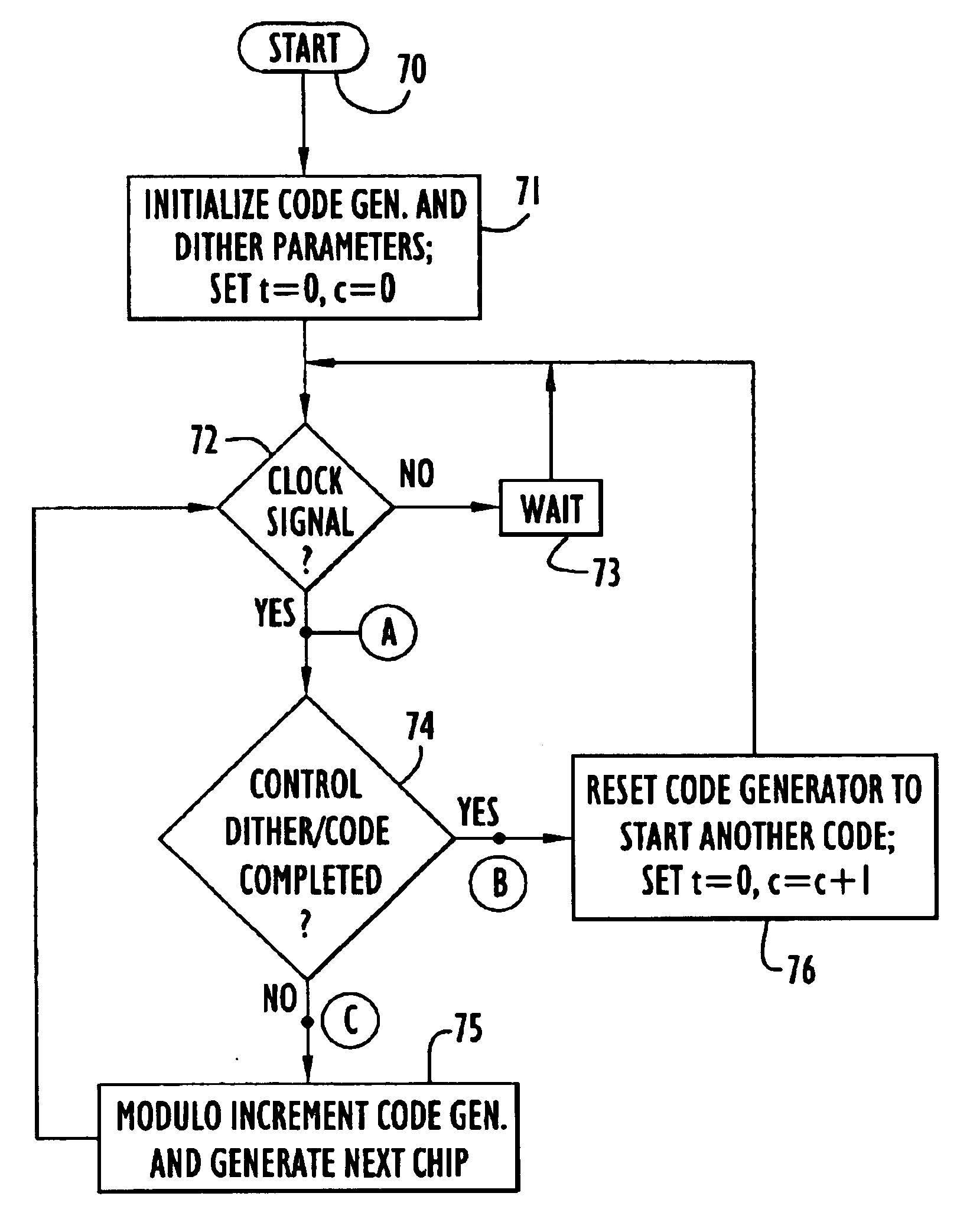
According to the present invention, a long code can be generated by using a reference code with good autocorrelation properties, such that a receiver can detect the long code without having to correlate each phase of the long code concurrently with parallel correlators, or over time over the entire period of the long code. Rather, the code can be quickly detected by using a reasonable number of correlators, similar to the number of correlators that would be used to detect the reference code. The long code is generated by repeating the reference code with a fixed pattern of phase variations called dither. Various types of dither can be used, as described below in detail. Also, certain methods described here generate optimal dither patterns where the autocorrelation of the long code is ideal if the autocor...


PUM


Abstract

A generator generates a composite code from dithered copies of a reference code to form an optimal stationary dither code. The generator either dithers the length of the reference code to generate a boundary dither code composed of a series varying length short codes, or it dithers the phase of the reference code to generate rotation dither code composed of a series of fixed length short codes that vary in phase. The generator dithers the reference code according to a dither pattern. The composite code is an optimal dither code, having an optimal autocorrelation properties, by generating a dither pattern in which phase vectors for the constituent code are not repeated within the code.

Description

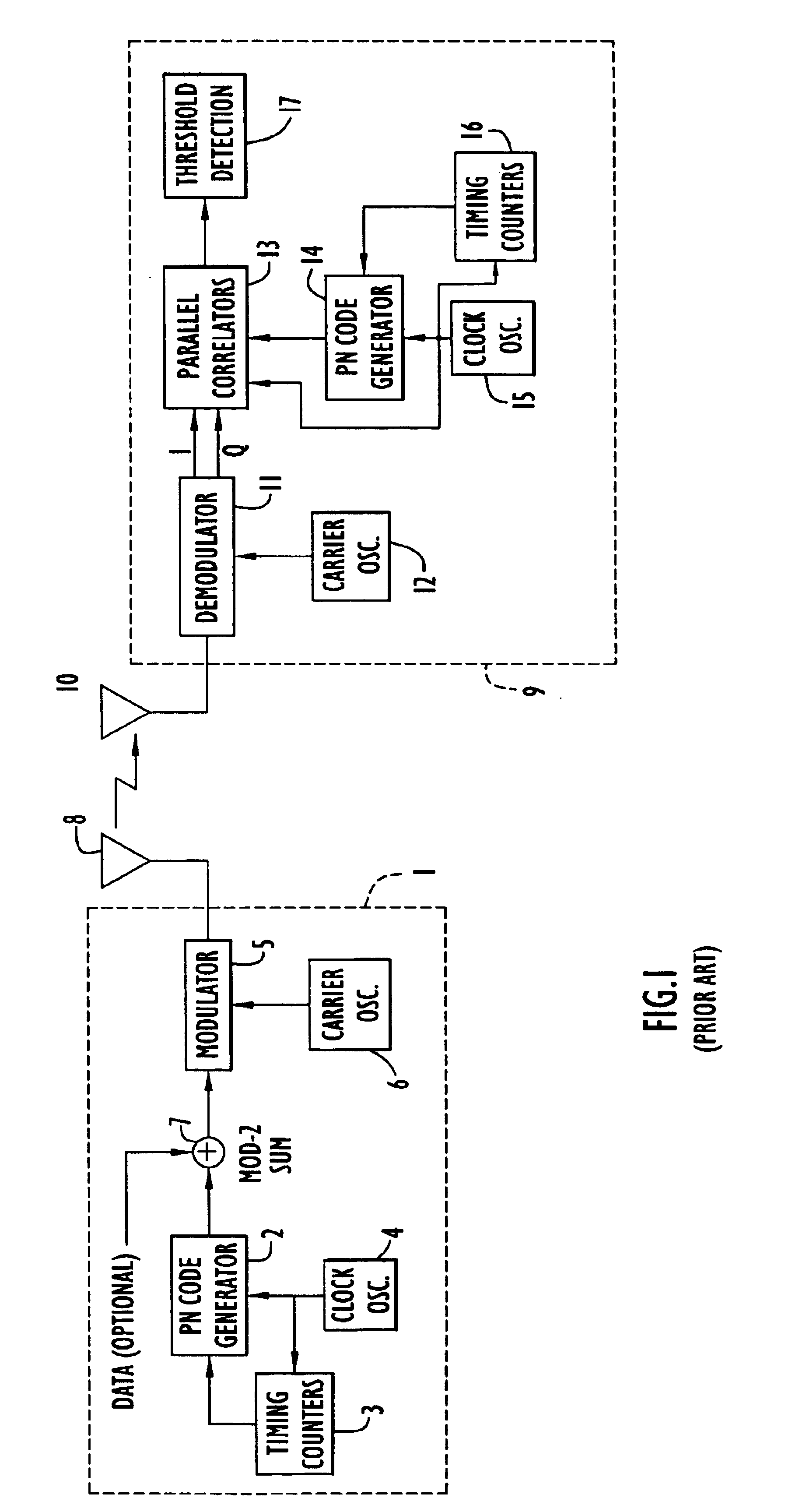
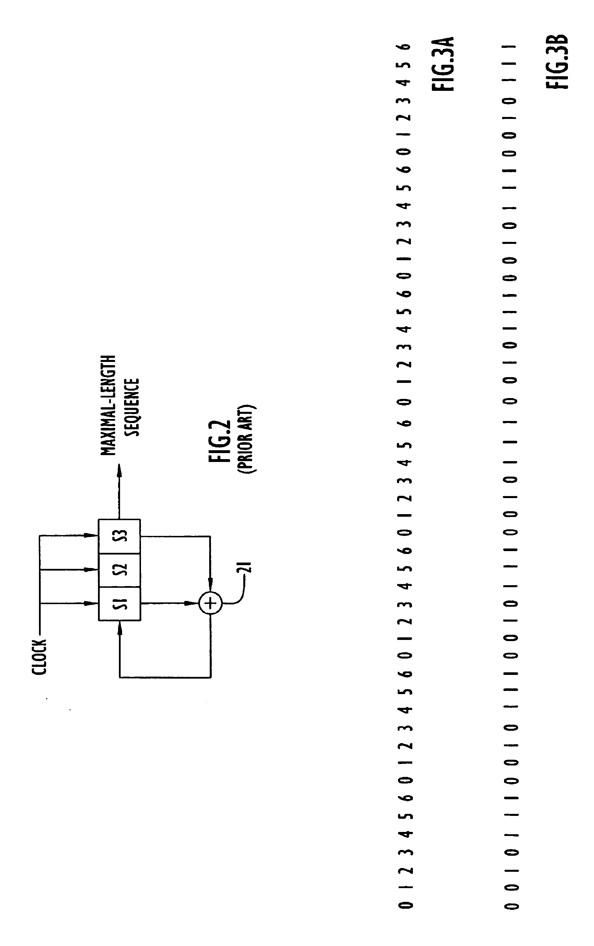
BACKGROUND OF THE INVENTION1. Field of the InventionThe present invention relates to data communication and timing systems and, more particularly, to data communication and timing systems using codes with coding boundaries that vary according to a dithering pattern.2. Description of the Related ArtPseudonoise (PN) codes, also known as pseudorandom codes, have good autocorrelation properties and are ideal for measuring the time-of-arrival of a signal, and hence, for use in ranging applications. A high coding gain is achieved when a receiver correlates the code, such as a PN code, for a long time. Accordingly, long PN codes have been used to provide high coding gain.An example of using a long PN code is in the Global Positioning System (GPS). GPS is a satellite-based navigation system in which each satellite in the GPS constellation transmits a unique precision (P) code. Each P code is a very long PN code that has a period of one week, and hence, repeats only once per week. The P code...

Claims


Application Information

Patent Timeline
IPC IPC(8): H04B1/69H04J13/00
CPCH04J13/10H04J13/0022
Inventor CLARK, JAMES M.
Owner EXCELIS INC
Learn More