
Visual lossless image compression

a lossless image and compression technology, applied in the field of image compression, can solve the problems of insufficient and achieve the effect of reducing the cost of time, memory and bandwidth requirements

Inactive Publication Date: 2005-03-15
MEICOM +1
View PDF49 Cites 32 Cited by
  • Summary
  • Abstract
  • Description
  • Claims
  • Application Information

AI Technical Summary

Benefits of technology

"The present invention provides an image compression method that separates an image into color channels and processes each channel separately using discrete cosine transformation or wavelet transformation. The method also predicts the value of a pixel based on the surrounding pixels and encodes the prediction error. The predicted value is formed by averaging the values of a majority of pixels in a diamond-shaped grouping. The method can produce a compressed image with a smaller file size and improved image quality."

Problems solved by technology

Some of these techniques are “lossless,” meaning that they preserve all information of the original image so that it is reproduced exactly when the data is decompressed.
To transmit or store such images in the uncompressed state (i.e., in the spatial or pixel domain) is simply too costly in terms of time, memory, and bandwidth requirements.

Method used


Image

  • Visual lossless image compression
  • Visual lossless image compression
  • Visual lossless image compression

Examples


Embodiment Construction

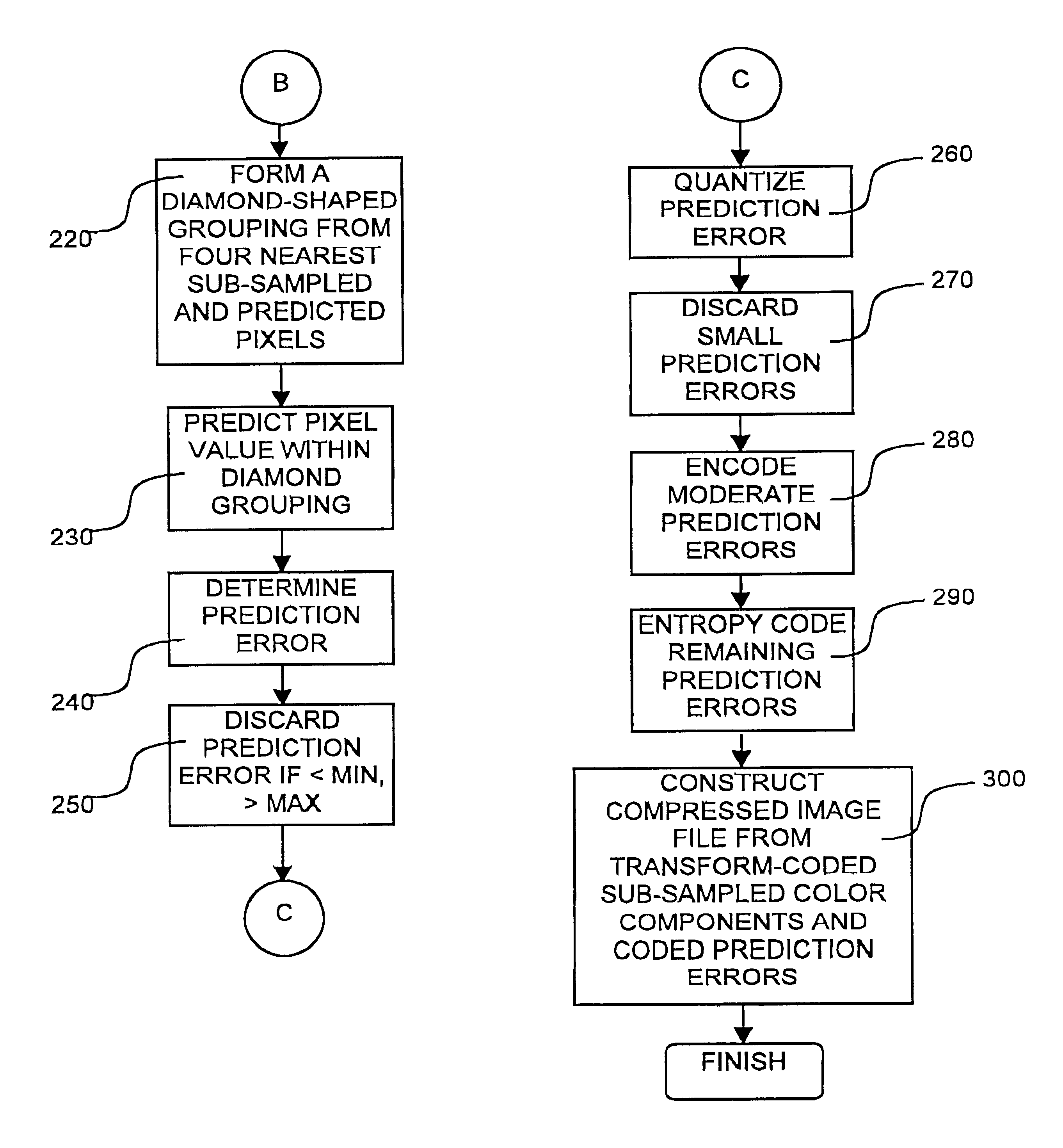
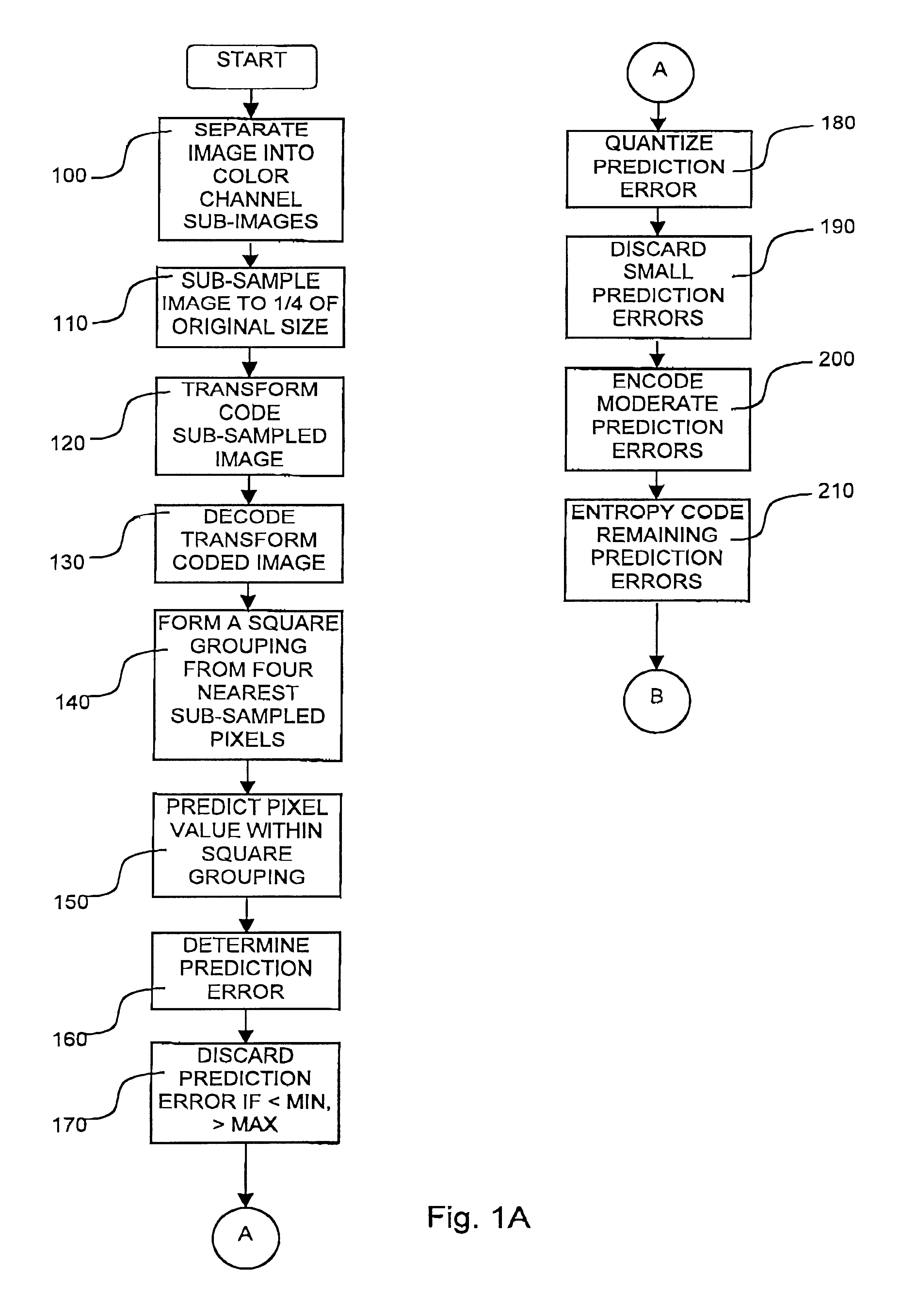
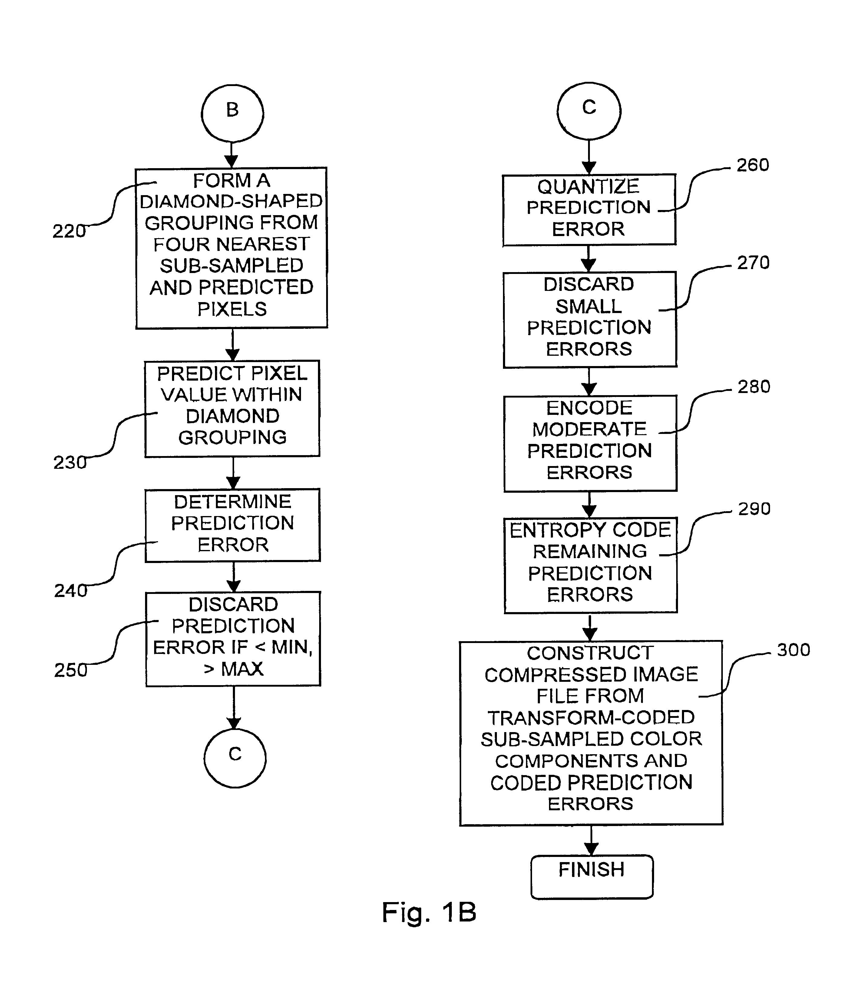
Reference is now made to FIGS. 1A and 1B, which, taken together, are simplified flowchart illustrations of an image compression method, operative in accordance with a preferred embodiment of the present invention, and FIGS. 2A-2E which are simplified pictorial illustrations of a portion of an image file useful in understanding various stages of the method of FIGS. 1A and 1B. In the method of FIGS. 1A and 1B a color or grayscale image file is separated into distinct color channel sub-images, such as red (R), green (G) and blue (B) in RGB color space or luminance (Y), chrominance (Cb) and chrominance (Cr) in YCbCr color space (step 100). Should the subject image file be stored in a compressed format, such as JPEG, the image is preferably decoded prior to color separation, Subsequent steps of the method of FIGS. 1A and 1B are then performed separately for each color channel sub-image, and references to “the image” may be understood as referring to the particular color component of the ...


PUM


Abstract

An image compression method is provided including separating an image into a plurality of color channel sub-images processing each of the color channel sub-images by sub-sampling the sub-image transform coding the sub-sampled sub-image decoding the transform-coded image forming a plurality of square groupings of pixels in the decoded image predicting a value for a pixel within each of the x-shaped groupings determining a prediction error for each predicted pixel value within each of the square groupings coding the prediction error forming a plurality of at least partly diamond-shaped groupings of pixels in the decoded image predicting a value for a pixel within each of the diamond-shaped groupings and combining each of the processed color channel sub-images with the coded prediction errors, thereby forming a compressed image.

Description

FIELD OF THE INVENTIONThe present invention relates to image compression in general, and more particularly to visual lossless image compression.BACKGROUND OF INVENTIONVarious image compression techniques have been proposed to reduce the amount of data used to represent a digitized color image while, at the same time, providing quality image representation. How much the image is compressed, given in terms of a compression ratio, depends on the image itself, the technique used and the amount of information loss that can be tolerated. Some of these techniques are “lossless,” meaning that they preserve all information of the original image so that it is reproduced exactly when the data is decompressed. Other techniques, commonly referred to as “lossy,” discard information which is visually insignificant. By only approximating the original image rather than reproducing it exactly, lossy techniques are generally able to produce higher compression ratios than lossless techniques. In select...

Claims


Application Information

Patent Timeline
Patent Type & Authority Patents(United States)
IPC IPC(8): G06T9/00H04N7/26H04N7/30H04N11/04H03M7/30H03M7/36H03M7/40H04N1/41H04N7/32
CPCH04N19/186H04N19/60
Inventor SADEH, RONI M.
Owner MEICOM
Learn More