Travel control system for vehicle

a technology for controlling systems and vehicles, applied in the direction of navigation instruments, driver input parameters, external condition input parameters, etc., can solve the problem of large vehicle position error

Inactive Publication Date: 2005-03-15
NISSAN MOTOR CO LTD
View PDF7 Cites 32 Cited by
  • Summary
  • Abstract
  • Description
  • Claims
  • Application Information

AI Technical Summary

Benefits of technology

However, since this earlier art is arranged to detect a vehicle position from information of the car navigation system, an error of the vehicle position tends to become large. Therefore, this system has been arranged to set the deceleration for a curve traveling at a small value so as to prevent a vehicle occupant from having strange feeling in a vehicle deceleration even if there is caused an inappropriate starting of the vehicle deceleration due to a large error in the vehicle position.

Problems solved by technology

However, since this earlier art is arranged to detect a vehicle position from information of the car navigation system, an error of the vehicle position tends to become large.

Method used


Image

  • Travel control system for vehicle
  • Travel control system for vehicle
  • Travel control system for vehicle

Examples


first embodiment

Referring to FIGS. 1 through 7, there is shown the travel control system for a vehicle according to the present invention.

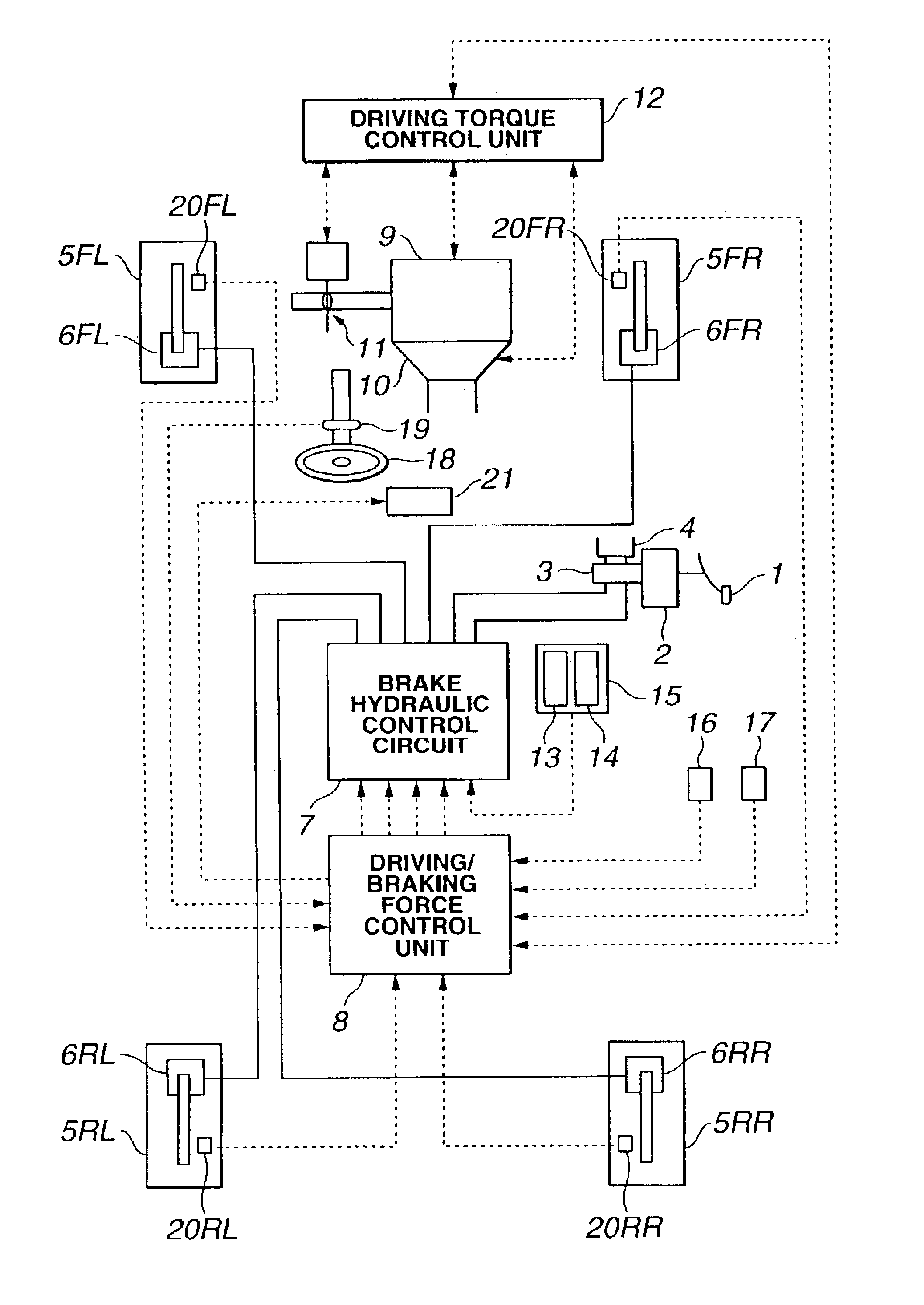
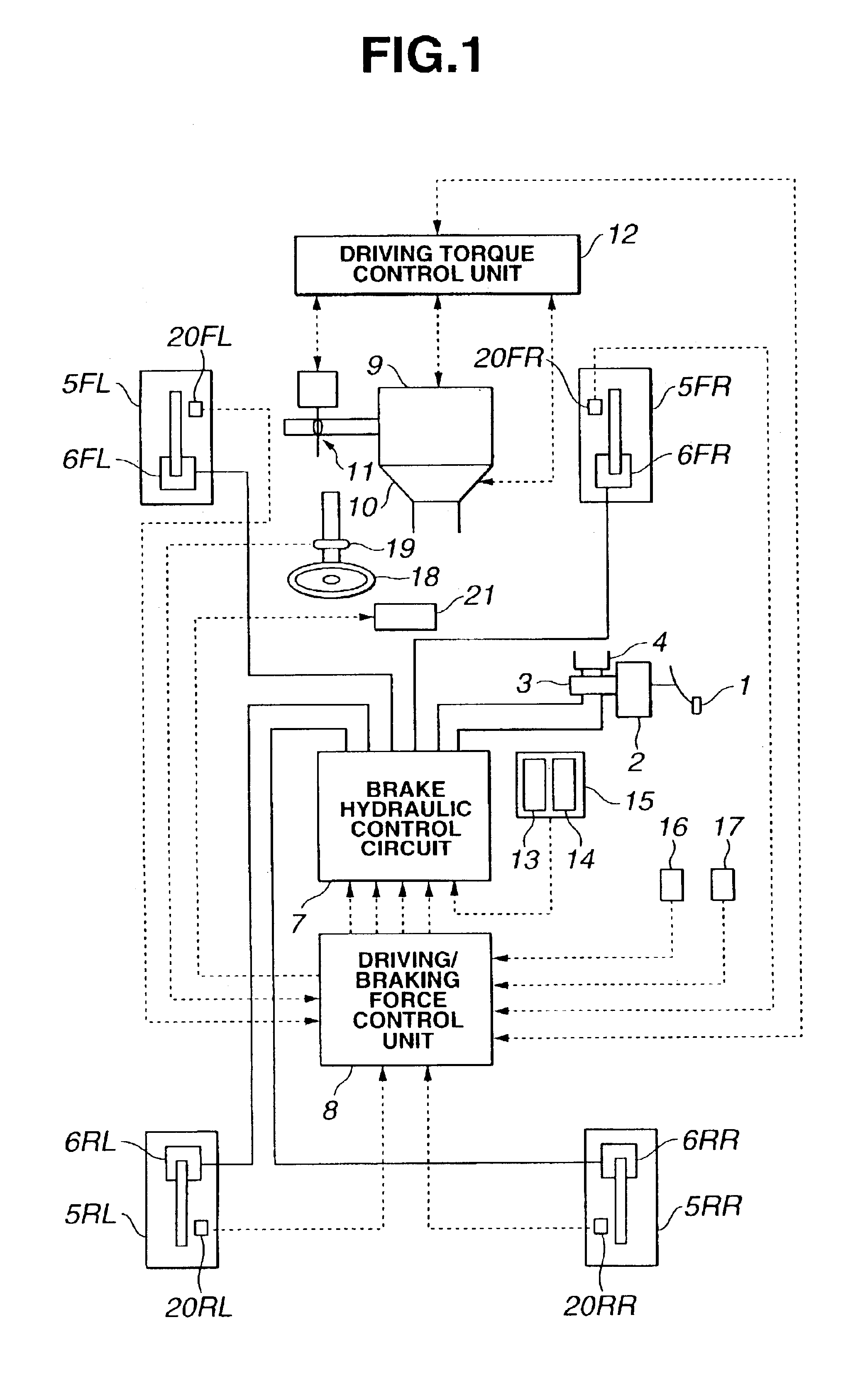
As shown in FIG. 1, the vehicle of a rear-wheel drive type is equipped with an automatic transmission and a conventional differential gear. The vehicle comprises a brake system which is capable of independently controlling a braking force of each of front-left, front-right, rear-left and rear-right wheels 5FL, 5FR, 5RL and 5RR. The brake system comprises a brake pedal 1, a booster 2, a master cylinder 3 and a reservoir 4. Normally, each of wheel cylinders 6FL, 6FR, 6RL and 6RR of the respective wheels 5FL, 5FR, 5RL and 5RR receives brake hydraulic pressure pressurized by master cylinder 3 according to a depression degree of brake pedal 1 depressed by a driver. Further, a brake hydraulic control circuit 7 is provided between master cylinder 3 and each of wheel cylinders 6FL, 6FR, 6RL, and 6RR so as to be capable of independently controlling the hydraulic pressure ...

second embodiment

Referring to FIGS. 9 and 10, there is shown the travel control system according to the present invention.

The second embodiment is specifically arranged to execute the driving / braking force control on the basis of the reliability of the information detected by car navigation system 15. The processing of driving / braking force control unit 8 of the second embodiment is executed according to a flowchart of FIG. 9 instead of the flowchart of FIG. 2.

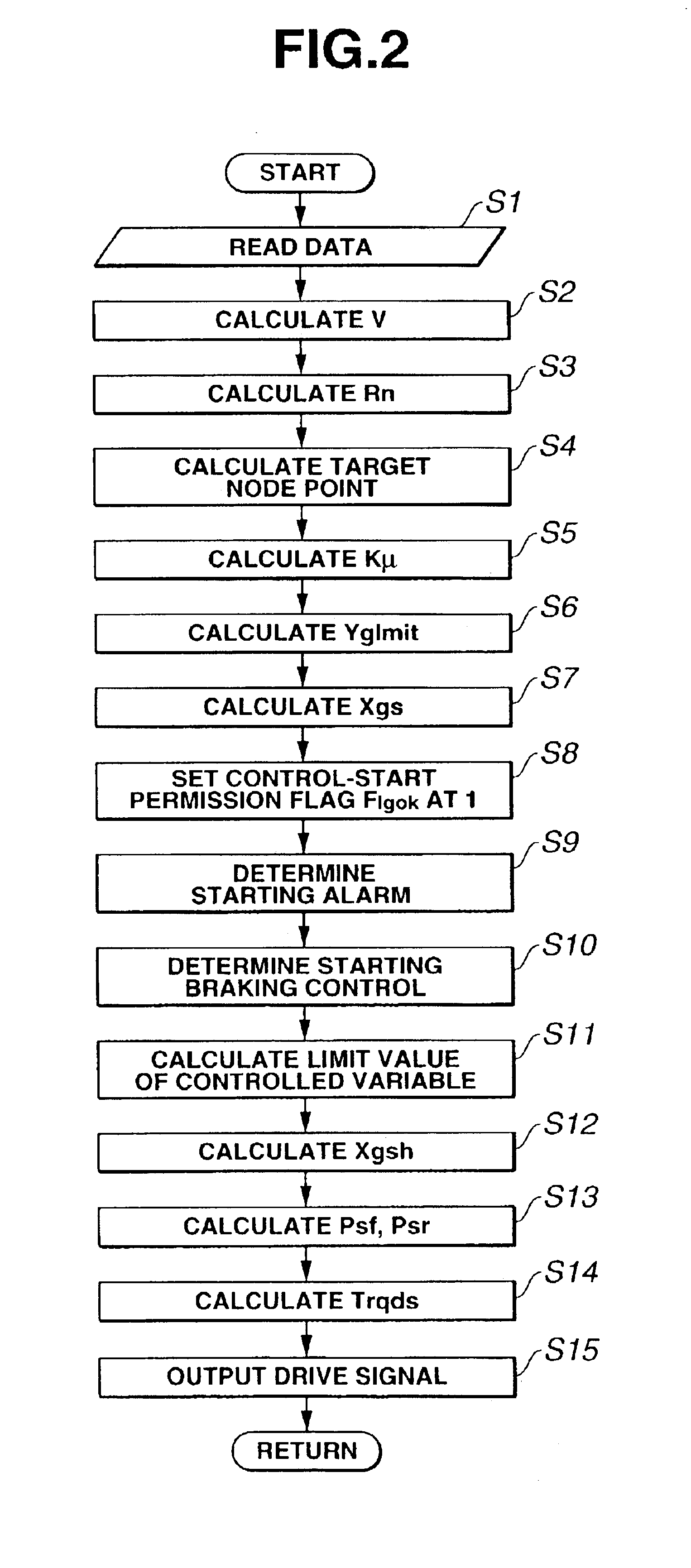
The processing of FIG. 9 includes steps that are the same as steps executed in the processing of FIG. 2, and therefore, the same steps are denoted by same references and the explanation thereof is omitted herein. The processing of FIG. 9 newly includes steps S16, S17 and S18 instead of step S11 of FIG. 2.

At step S16 subsequent to the execution of step S10, control unit 8 calculates an estimated steer angle θr, which is an estimate of steer angle θ steered by a vehicle occupant, on the basis of the node information of the vehicle position and t...

third embodiment

Referring to FIG. 10, there is shown the travel control system according to the present invention.

The third embodiment is arranged to employ a communication device 22 instead of car navigation system 15 shown in FIG. 1, as shown in FIG. 10. Communication device 22 obtains the node information by communicating with an infrastructure device, which is disposed at an entrance of a curve ahead of the vehicle and detects the node information (Xn, Yn, Ln), or an infrastructure device, which has previously stored the node information. The travel control system can executes the driving / braking force control on the basis of the curve information.

In this third embodiment, communication device 22 functions as a curve information detecting means.

With the thus arranged third embodiment, control unit 8 receives the curve information from one of the infrastructure device, which is disposed at an entrance of a curve ahead of the vehicle and detects the node information (Xn, Yn, Ln), and an infrastru...


PUM


Abstract

A vehicle travel control system is arranged to obtain curve information as to a curve of a road ahead of the vehicle, to obtain a vehicle driving condition produced by a vehicle occupant, to obtain a curve entering degree of the vehicle into the curve on the basis of the driving condition, to obtain a vehicle speed, and to decelerate the vehicle on the basis of the curve information and the curve entering degree and the vehicle speed.

Description

BACKGROUND OF THE INVENTIONThe present invention relates to a travel control system for a vehicle, and more particularly to a travel control system, which controls a vehicle on the basis of road information obtained from a car navigation system.Japanese Patent Provisional Publication No. 4-236699 discloses a travel control system using road information stored in a car navigation system. This travel control system is arranged to detect a curve shape of a road ahead of a vehicle and to decelerate the vehicle according to the curve shape when the vehicle enters the curve.SUMMARY OF THE INVENTIONHowever, since this earlier art is arranged to detect a vehicle position from information of the car navigation system, an error of the vehicle position tends to become large. Therefore, this system has been arranged to set the deceleration for a curve traveling at a small value so as to prevent a vehicle occupant from having strange feeling in a vehicle deceleration even if there is caused an i...

Claims


Application Information

Patent Timeline
Patent Type & Authority Patents(United States)
IPC IPC(8): B60K31/00B60T8/1755B60T8/17G01C21/00B60R21/00B60T7/12B60W10/00B60W10/04B60W10/06B60W10/10B60W30/00F02D29/02F16H59/44F16H59/66F16H61/02F16H63/50G01C21/26G08G1/16
CPCB60K31/0066B60T8/1755B60T2201/16B60W2720/125B60T2210/36B60W2520/125B60W2550/143B60T2210/24B60W2540/18B60W2552/20B60W2552/30
Inventor MATSUMOTO, SHINJINAITO, GENPEITANGE, SATOSHI
Owner NISSAN MOTOR CO LTD
Why Eureka
Try Eureka